|
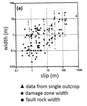
It is widely accepted that fault zone and fault rock width or thickness will increase as slip on a fault progressively accumulates and the fault grows longitudinally and laterally. However, the exact nature of this relationship is not very clear. It is proposed that the scaling relationship between fault throw and fault zone thickness is roughly between 1:10 and 1:100 in sandstone and sandstone/shale of Nubian Sandstone formation in western Sinai (Figure 1 from Knott et al. 1996).
 | | Figure 1. Fault Zone Thicknesses distribution in Nubian Sandstone Formation in western Sinai. From Knott et al. (1996). The authors concluded that juxtaposition involving sandstone and shale lie along a trend with Thickness-Throw ratio of 1:100 and sandstone-sandstone ratio of 1:10. The authors haven't identified specific failure mechanisms responsible for this difference. |
However, thickness of fault zones and fault rocks and the failure mechanism leading to faulting have not been unambiguously identified in many early studies. Myers and Thompson (1998) paid particular attention to these aspects in their study of faults formed by shearing of joint zones in Aztec Sandstone exposed at Valley of Fire State Park, Nevada (Figures 2 and 3). These authors found scaling relationships closer to 1:10 than 1:100. They also proposed that the initial joint zone configuration influences the trends. For example, initial joint zone configurations composed of echelon joints with a certain arrangement may have a different trend (the upper line in the plot in Figure 3) than that from a configuration of sub-parallel joints.
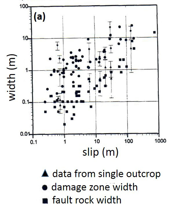
 | | Figure 2. Width versus slip for fault rock and fault damage zone along three scan lines originally measured by R. Myers across a series of faults in Aztec Sandstone in Valley of Fire State Park (NV). Note that these faults formed by shearing of joints and joint zones and a majority of them are strike-slip (see Flodin and Aydin, 2004; Myers and Aydin, 2004), but some have normal components, and there fore, some of the slip is apparent. From Myers and Thompson (1998). |
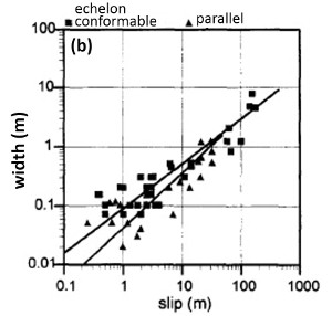 | | Figure 3. Fault rock width versus slip as a function of the initial joint zone architecture. Full rectangles for fault rocks formed by shearing of echelon conformable joint zones and full triangles for those made primarily by shearing of joint zones with parallel joints. From Myers and Thompson (1998). |
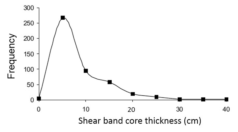
It is proposed that scaling relationships of shear band faults are different than those faults formed by different mechanisms (Fossen and Westhammer, 1997). Figure 4 is a displacement or slip versus thickness plot for faults formed as shear bands in sandstone exposed at the San Rafael Swell (Shipton et al., 2005). The largest thickness appears to be about 40 cm, meaning that most faults are rather small. Figure 5 displays shear band thickness in detrital rocks with different grain size distribution formed by different mechanisms (Fossen et al., 2007). Strain localization by cataclastic deformation mechanism in fine- to course-grained sandstones produces different band thicknesses, i.e., narrow band thickness corresponding to those formed by cataclastic mechanisms in fine-grained rocks.
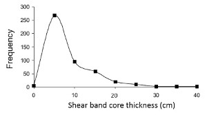 | | Figure 4. Shear band thickness distribution, outcrops in the San Rafael Swell, Utah. It appears that the shear band thickness is capped by about 40 cm. From Shipton et al. (2005). |
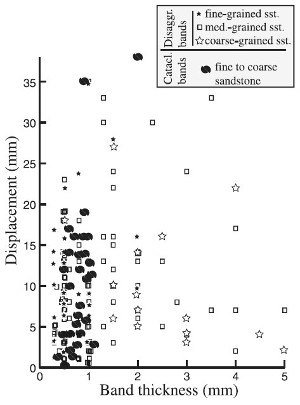 | | Figure 5. Thickness distribution of shear band faults with different micromechanics in sandstones of various properties. From Fossen et al. (2007). |
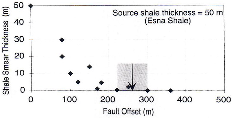
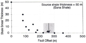
Shale fault rocks which are known as smeared shales in the energy industry have thickness-slip distribution trending opposite to those presented above. The thickness of smeared shales along faults with increasing offsets decreases and eventually the thickness is reduced to zero locally. The plot in Figure 6 is for the Esna Shale exposed on the Gulf of Suez, normally about 50 meters thick when undisturbed, but the thickness of shale fault rock derived from this formation is locally zero beyond about the 200 to 250 meter range (Figure 7, Younes and Aydin, 1998).
 | | Figure 6. Distribution of smeared shale thickness across normal faults with increasing offsets in eastern Gulf of Suez, Egypt. The original thickness of the undisturbed Esna Shale is 50 meters. The thickness decreases as the offset increases and beyond 200-250 meters offset the continuity of shale fault rock is broken down. From Younes and Aydin (1998). |
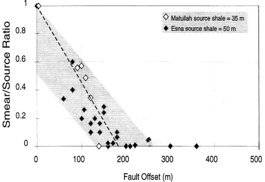
 | | Figure 7. Shale smear thickness (normalized by the original formation thicknesses) decreases as a function of fault offset for two faults in the Gulf of Suez, Egypt. The original undisturbed thicknesses of the shale units were 35 and 50 meters. Data from Younes and Aydin 1997; 1998. |
| |
Evans, J.P., 1990. Thickness-displacement relationships for fault zones. Journal of Structural geology 12: 1061-1065.
Flodin, E.A., Aydin, A., 2004. Faults with asymmetric damage zones in sandstone, Valley of Fire State Park. Journal of Structural Geology 26: 983-988.
Fossen, H., Hesthammer, J., 1997. Geometric analysis and scaling relations of deformation bands in porous sandstone. Journal of Structural Geology 19(12): 1479-1493.
Fossen, H., Schultz, R.A., Shipton, Z.K., Mair, K., 2007. Deformation bands in sandstone: a review. Journal of the Geological Society 164: 755-769.
Knott, S.D., Beach, A., Brockbank, P.J., Brown, J.L., McCallum, J.E., Welbon, A.I., 1996. Spatial and Mechanical controls on normal fault population. Journal of Structural Geology 18: 359-372.
Myers, R., Thompson, L.B., 1998. Fracture clustering associated with faults formed from joint zones in sandstone. Stanford Digital Repository. Available at: http://purl.stanford.edu/zk915qm4858.
Myers, R., Aydin, A., 2004. The evolution of faults formed by shearing across joint zones in sandstone. Journal of Structural Geology 26 (5): 947-966.
Shipton, Z.K., Evans, J.P., Thompson, L.B., 2005. The geometry and thickness of deformation band fault core and its influence on sealing characteristics of deformation band fault zones. in R. Sorkhabi and Y. Tsuji, eds, Faults, fluid flow, and petroleum traps: AAPG Memoir 85: 181 - 195.
Younes, A.I., Aydin, A., 1998. Gulf of Suez Field Trip Guidebook. The Stanford Shale Smear Project 1998 Field Trip Guide. Stanford Digital Repository. Available at: http://purl.stanford.edu/jp025yc8745.
|