| ||||||||||||||||||||||||
|
|
||||||||||||||||||||||||
|
|
||||||||||||||||||||||||
| Growth of Faults based on Folding and Thrusting of Multilayers | ||||||||||||||||||||||||
|
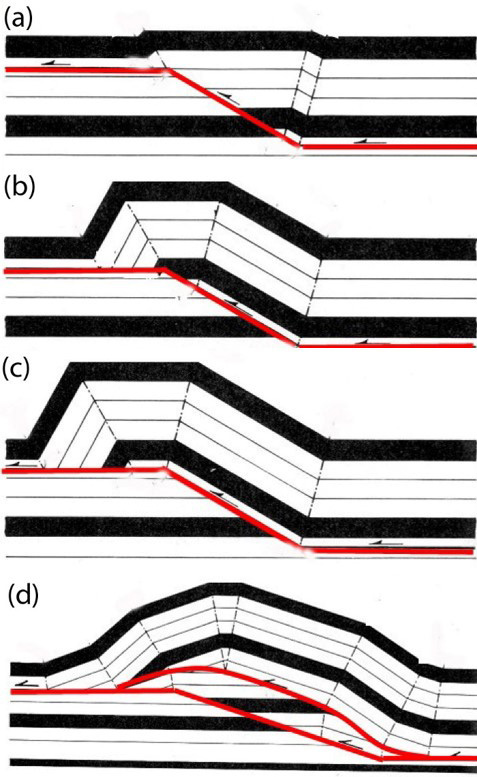
We previously discussed the growth of primarily strike-slip faults in a massive and relatively stiff rock unit, an aeolian sandstone. Suffice it to say that the mechanism of other types of faults with various types of dip-slip in rheologically similar rocks under similar conditions should be the same with only certain variations in the orientations of the structural components, which have been described somewhere else in this Knowledgebase. However, the growth of dip-slip faults in multi-layered rocks with alternating stiff (competent-brittle) and soft (incompetent-ductile) lithologies involves different mechanisms. One of these, under compression, produces bedding plane faults or decollements in soft intervals and segments at high-angle to bedding or ramps in stiff intervals. In addition, such a sequence is prone to folding. If the fault steps up from a lower decollement to a higher one cutting up a stiff layer, the thrust fault lengthens and the hanging wall deforms by bending (Figures 1(a), (b), (c)) producing the so-called fault bend folds (Suppe, 1985). It is common that the fault zone gets wider and more complex including multiple fault strands in an imbricated geometry (Figure 1(d), also see Boyer and Elliott (1982) for a wide variety of imbrication examples).
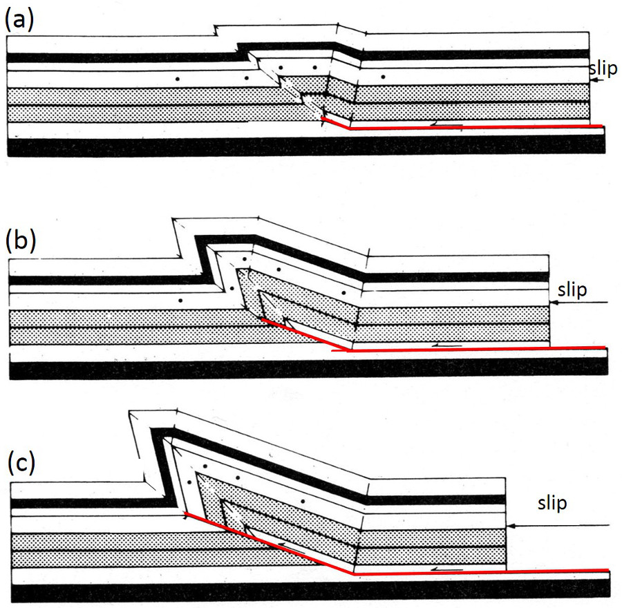
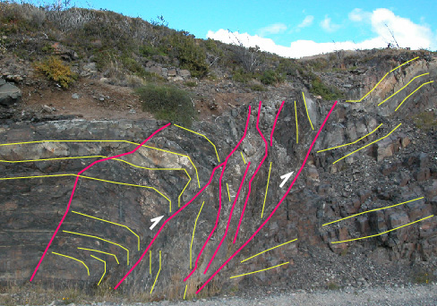
Another fault related deformation occurs when a thrust fault starting as a bedding plane fault or decollement steps up and the upper tip of the fault is confined within the sequence resulting in a so-called fault propagation fold (Figures 2(a), (b), (c)). The triangular limb is also referred to as a trishear zone (Ersley, 1991). Sometimes, the steeper limb of a fold is cut off and rotated between sub-parallel thrust faults along the axial surfaces producing a wider rectangular fault zone with a high-angle and locally overturned beds. Such a strikingly different dip domain between closely spaced thrust faults can be seen in an outcrop map from Chilean Patagonia (Figure 3).
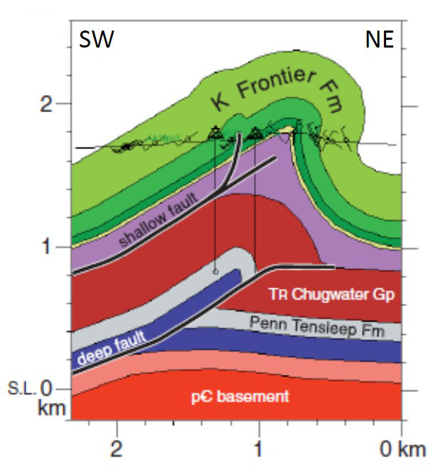
Perhaps somewhat more relevant to the focus of this Knowledgebase is how the fault-related folding process influences the associated fracture distribution. We provide two examples for the application of the concepts to fracturing and faulting in fault-related folds. The representative cross-section of the Oil Mountain anticline in Wyoming, Figure 4 and Figure 5, has two levels of decollements at the subsurface inferred from seismic data by Henning et al. (2000) and displays one of these applications.
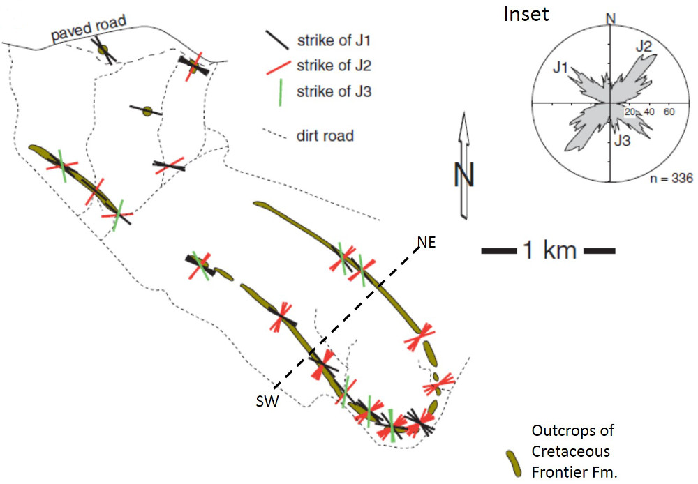
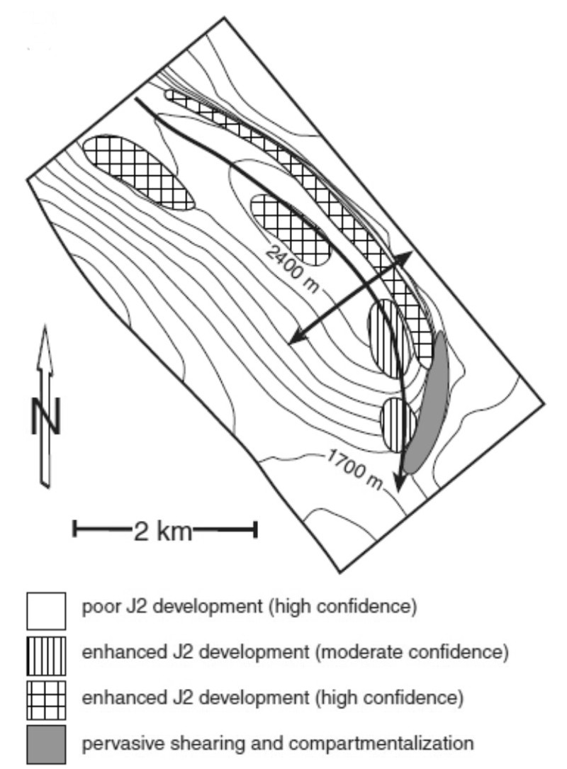
Figure 6 is an outcrop map of Cretaceous Frontier Formation sandstone with the fracture orientations measured in the field. The fracture data both in the map and in the rose diagram (inset) show two orthogonal fracture sets (31 and 32) and another set (33) oblique to both orthogonal sets. It has been noted by the authors that the J1 set doesn't show a significant variation in intensity across the fold but the J2 set at high-angle to bedding strike has extremely intense distribution in some areas. Figure 6 is a structure map showing schematically the locations of the enhanced fracture developments related to the fault-related folding. Also noted is a system of pervasive shear fractures at the nose of the fold structure.
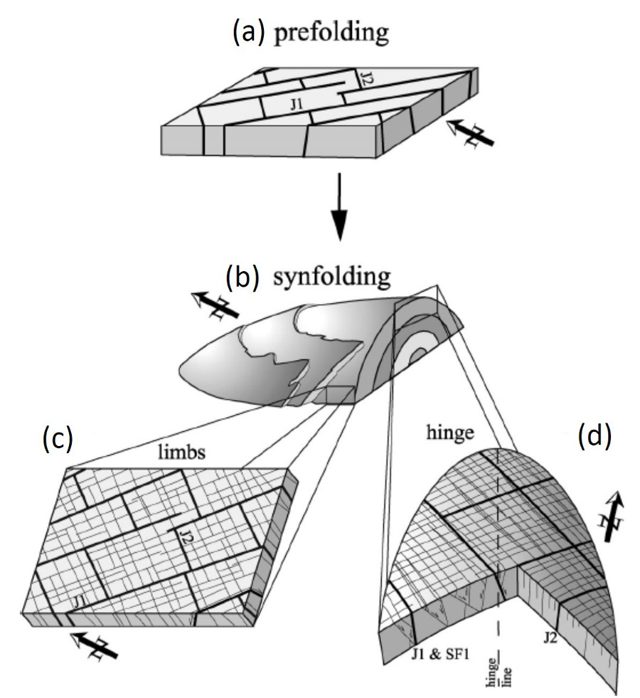
A series of maps and schematic diagrams in Figures 7 ((a) to (d)) illustrate surface fracture distribution at the Emigrant Gap anticline, about 15 km northeast of the Oil Mountain anticline. The authors, Bergbauer and Pollard (2004), proposed that two nearly orthogonal sets of joints (J1 and J2) formed before folding (7(a)) and they are rarely parallel and perpendicular to the local fold hinge lines (7(b) to (d)). These joint sets, however, experienced minor shearing at the limb areas. However, the joint sets, particularly the J2 set, show noticeable larger shearing within the fold hinge area, where the J2 set is closer to the local orientation of the fold hinge lines (7(d)). The authors attributed this increase to fold-related deformation.
For what it's worth, we would like to note our own experience on the fracture distributions across fault-related folds though with less certain underlying thrust fault geometry (Florez-Nino et al., 2005; Antonellini et al., 2008; and Cilona et al, 2015). First, it should be kept in mind that fractures in such environments are strongly controlled by the depositional architecture. Therefore, fracture spacing or intensity would only be meaningful if the thicknesses of the brittle sequences, which are generally hierarchical, are established preferably using sequence stratigraphy. Second, most initial opening mode fractures in stiff layers have zonal characters and it is more appropriate to establish the nature of their clustering. Third, even though initially opening mode fractures may have been strata-bound, any progressive deformation, and particularly, tilting and rotation of fold limbs, would introduce shearing across them which would result in linking of initial vertical fractures in nearby stiff layers, and thereby increasing the heights (and also lengths) of the connected faults. The vertical and lateral continuity of these faults of various size and their statistical properties would be a function of the progressive shearing and the aggregate slip magnitude across the underlying thrust and the related fold structure as well as the depositional architecture. Interested readers are referred to the related references below. | ||||||||||||||||||||||||
| Reference: |
||||||||||||||||||||||||
| Antonellini, M., Tondi, E., Agosta, F., Aydin, A., Cello, G., 2008 Bergbauer, S., Pollard, D.D., 2004 Erslev, E.A., 1991 Florez-Nino, J.M., Aydin, A., Mavko, G., Antonellini, M., Ayaviri, A., 2005 Henning, P., Olson, J., Thompson, L.B., 2000 Suppe, J., 1985 |
||||||||||||||||||||||||
|
Readme | About Us | Acknowledgement | How to Cite | Terms of Use | Ⓒ Rock Fracture Knowledgebase |
||||||||||||||||||||||||