| |||||||
|
|
|||||||
|
|
|||||||
| Assemblages of Joints and Faults | |||||||
|
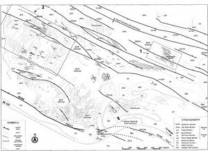
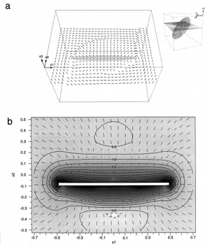
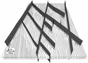
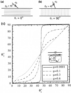
This is one of the most common assemblages in nature and was dealt with in great detail somewhere else in this Knowledgebase. Please see the links entitled 'Splay Joints,' 'Faulting by Shearing of Single Set of Joints,' and 'Faulting by Shearing of Orthogonal Sets of Joints.' Here we review some results which have the same characteristics of fracture networks involving various types of faults and the related joints. Figure 1 is a map showing a network of normal faults and joints in sandstone at Arches National Park, Utah. It shows many characteristics of faults and related joints, two end members of which are parallel and orthogonal trace geometries. Kattenhorn et al. (2000) interpreted these patterns in terms of perturbed stress fields due to the fault slip (Figure 2). One of the best studied fault-joint patterns is that of the Bristol Channel fracture network. Figure 3 shows a schematic diagram demonstrating strike-slip faults and the related joints. Rawnsley et al. (1992 and 1998), Petit et al. (2001), Bourne and Willemse (2001), and Maerten et al. (2006) studied the fault-joint patterns using a mechanical model based on elastic dislocations with extended sensitivity analyses. Again, it is straightforward to notice joints occurring sub-parallel to the faults in some areas, but in the central area of the diagram more complex intersection relationships including orthogonal and low-angle diagonal intersections are apparent. Ohlmacher and Aydin (1997) upon observing orthogonal and sub-parallel joints (and veins) and thrust faults, proposed that the frictional properties of the faults play an important role in the network patterns. Figures 4(a) and (b) provide a simplified version of their model for frictionless or very low friction coefficient along the faults to explain dual behavior of such a system as a function of the two most common angular relationships between the greatest compressive stress and the faults. For angles smaller than 45 degrees, the parallel fault-joint patterns are favored. For angles larger than 45 degrees, orthogonal fault-joint patterns are favored. Figure 4(c) is a plot showing the orientation of the local greatest compression as a function of the friction coefficient at mid points between two parallel faults. The fact that faults are segmented in every scale suggests that fault tip lines play an important role in splay geometry and consequently in fault-joint relationships (Crider and Pollard, 1998). To this end, the readers are referred to the 'Splay Joints' and 'Fault Damage Zones' links given below. | |||||||
| Reference: |
|||||||
| Bourne, S.J., Willemse, E.J.M, 2001 Crider, J.G., Pollard, D.D., 1998 Dee, S.J., Yielding, G., Freeman, B., Healy, N.J., Kusznir, N., 2007 Kattenhorn, S., Aydin, A., Pollard, D.D., 2000 Maerten, L., Gillespie, P.A., Daniel, J.M., 2006 Ohlmacher, G., Aydin, A., 1997 Rawnsley, K.D., Rives, T., Hencher, S.R., Lumsden, A.C., 1992 Rawnsley, K.D., Peacock, D.C.P., Rives, T., Petit, J.P., 1998 |
|||||||
|
Readme | About Us | Acknowledgement | How to Cite | Terms of Use | Ⓒ Rock Fracture Knowledgebase |
|||||||


