| ||||||||||||
|
|
||||||||||||
|
|
||||||||||||
| Mechanisms and Mechanics of Splay Faults | ||||||||||||
|
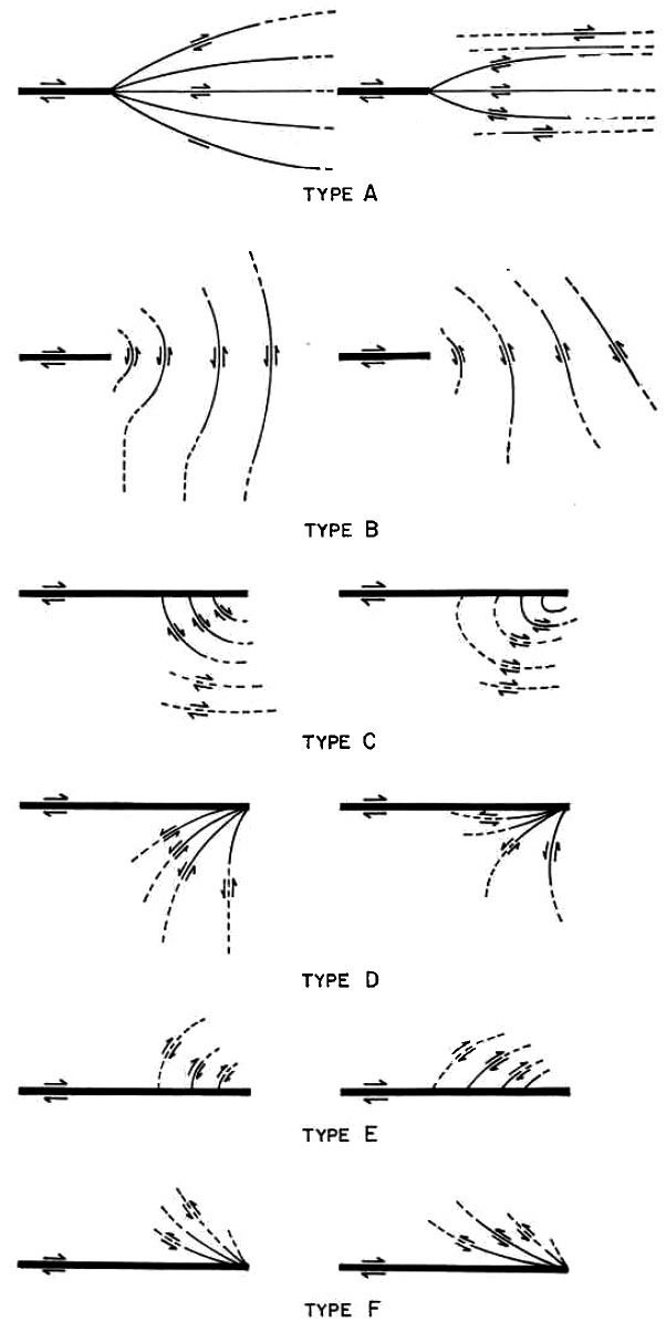
One of the earliest attempts to model splay or secondary faults was that of Chinnery (1966) who, using the dislocation model, calculated stress perturbation due to strike-slip faults in a medium subjected to pure shear and uniaxial compression. Chinnery, attributing to Anderson (1951), assumed that secondary faults would be most influenced by the maximum shear stresses and provided a wide variety of 2-D secondary fault trace geometries (Figure 1).
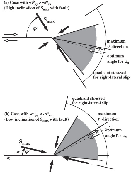
Commonly the term fault branch has been used within the context of dynamic deformation with high propagation velocity within the context of earthquake ruptures, their sequence, and directivity. In this case, rupture branching depends on the direction of principal stresses in the prestress state and rupture velocity (Poliakov et al., 2002; Kame et al., 2003). The latter authors also proposed that the most favored side for branching with respect to the end quadrants of the main mode II rupture switches from extensional to the compressional side as the angle between the direction of maximum compressive stress and the fault plane becomes smaller (Figure 2).
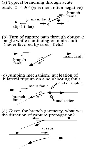
In the study of active faults, the primary objective is to understand and to analyze rupture propagation along pre-existing faults and the related instabilities. Another interesting conclusion in this context is that, even though the acute angle branching in the direction of the rupture propagation may be the most common configuration in nature, it is not the only potential rupture configuration according to Fliss et al. (2005). A summary of these authors' potential rupture propagation scenarios is presented in Figure 3. See also Dunham et al. (2011) for a 2-D (plane strain) model for plastic strain distribution around a conceptual strike-slip fault with fractal roughness under the link, 'Growth of Faults.'
| ||||||||||||
| Reference: |
||||||||||||
| Chinnery, M.A., 1966 Dunham, E.M., Belanger, D., Cong, L., Kozdon, J.E., 2011b Fliss, S., Bhat, H.S., Dmowska, R., Rice, J.R., 2005 Kame, N., Rice, J.R., Dmowska, R., 2003 |
||||||||||||
|
Readme | About Us | Acknowledgement | How to Cite | Terms of Use | Ⓒ Rock Fracture Knowledgebase |
||||||||||||