| |||||||||||||||||||||
|
|
|||||||||||||||||||||
|
|
|||||||||||||||||||||
| Upscaled Fault Porosity and Permeability | |||||||||||||||||||||
|
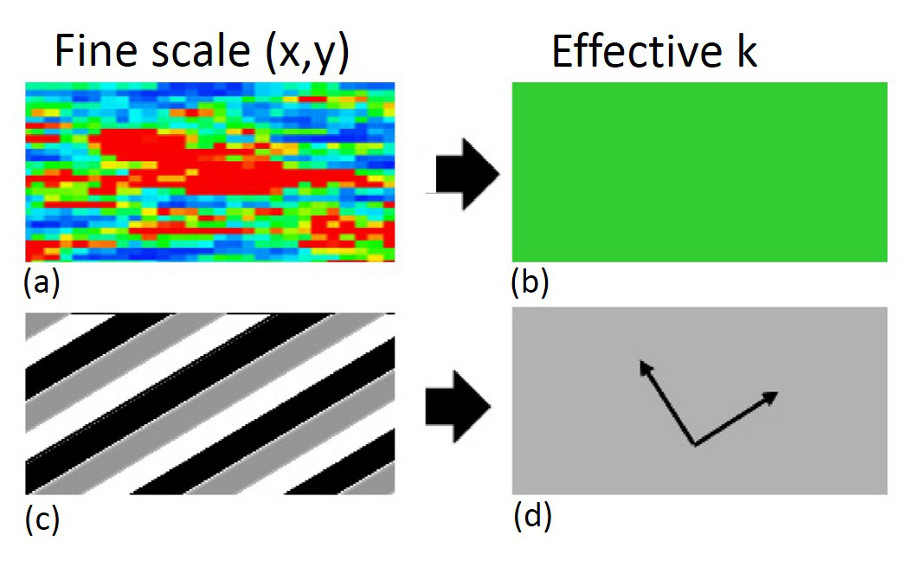
Upscaled or effective permeability is a homogeneous matrix such that flow rate is equal to that calculated from the fine scale flow equation for the same pressure difference (Figures 1(a) and (b)). Upscaled permeability is commonly anisotropic, reflecting the anisotropy of the depositional and deformational structures (Figures 1(c) and (d)).
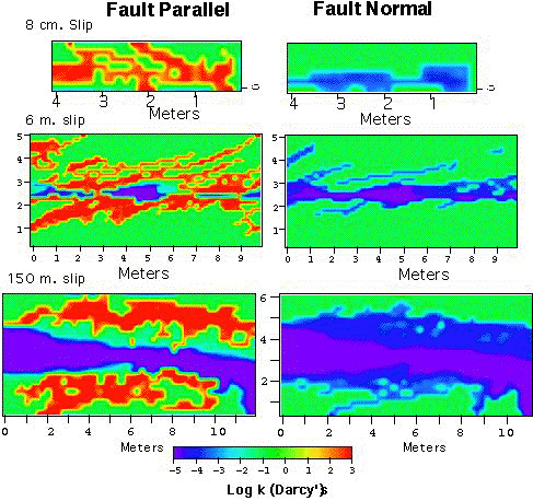
Myers (1997), using a simple method based on power averaging (Deutsch, 1989), calculated upscaled fault permeability for the same faults at the same location as mentioned above. This was done by calculating the volume fraction of each fault component from a map of the principle fault zone structures. Myers characterized the fault zone of a joint-based fault in porous sandstone as composed of fault rock, sheared joints, and joints. Host rocks and fault rocks form the matrix (Figure 2). The matrix permeability was first calculated from the combination of the volumetric fraction of fault rocks (low permeability component) and undeformed rocks (high permeability component) as shown in the equation given in Equation 1. Then, the permeability of the entire fault zone is calculated by combining the volumetric fraction of the matrix (low permeability component) and the sheared joints and joints (high permeability component). The resulting permeability map captures some important characterizations of fault zones: highly anisotropic in fault-normal and fault-parallel directions; decreasing fault-normal permeability with increasing slip; and increasing fault-parallel permeability with increasing slip.
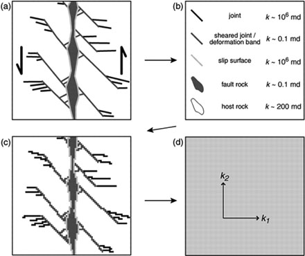
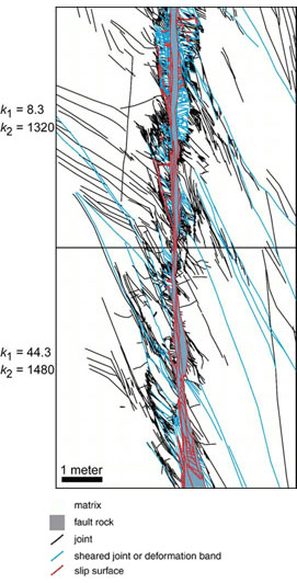
Manzocchi et al. (1999) provided another method for upscaling based on fault transmissibility multiplier and applied it to faults with fine-grained fault rock such as shale. Shipton et al. (2002) used this transmissibility multiplier method to model the upscaled permeability of a deformation band-based normal fault in Navajo Sandstone at northern San Rafael Swell, central Utah. See 'Porosity and Permeability of Shear Bands.' Upscaled permeability calculated this way is dependent primarily on the thickness of the fault core. Jourde et al. (2002) provided a procedure to upscale permeability of fault zones formed by the sheared joints mechanism in Aztec Sandstone at Valley of Fire, Nevada. A schematic diagram of their general workflow is shown in Figure 3. The bases of the procedure are sub-centimeter-scale resolution field maps that distinguish the various elements of the fault zone (Figure 3(a)). The permeability values of each fine-scale fault-zone element are either measured or estimated (Figure 3(b)) and then input into the detailed description (Figure 3(c)). Numerical simulation of the fine-scale input map yields the larger scale permeability of the fault zone of interest (Figure 3(d)). Their results show that upscaled permeability is drastically different along the fault zone than perpendicular to the fault zone. Fault-parallel permeability is typically up to one order of magnitude larger than that of the host rocks, but the fault-normal component is commonly two orders of magnitude smaller (Figure 4).
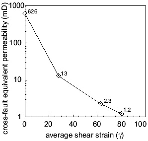
Following the methodology of Jourde et al. (2002), Flodin (2003) and Flodin et al. (2005) calculated upscaled cross-fault permeabilities at three fault locations with different shear strain and they are plotted in Figure 5. As a reference point, median host rock permeability, 626 mD, is plotted at 0. Upscaled cross-fault permeabilities show a decreasing trend, ranging between 1.2 and 13 mD, from low to high shear strain. These values indicate a one to two orders of magnitude reduction between fault core and median host rock permeability (626 mD). For each location, the upscaled fault-normal permeability was most influenced by the least permeable and most continuous body of fault rocks. These results show that sand-on-sand faults formed by shearing along joint zones in sandstone will act as baffles to subsurface fluid flow on production time-scales (tens of years).
Elena and Johnson (2004) measured the hydraulic head distribution and calculated the fault rock permeability in an aquifer-aquitard system offset by a normal fault with 20 meter displacement. The permeability of the aquifer is 500 mD and that of the aquitard is 0.01 mD. Where the fault juxtaposes aquifer against itself, the fault rock permeability is 10 to 30 mD. Where the aquifer is faulted against the aquitard, the fault rock permeability ranges from 0.01 to 3.0 mD. Within the aquitard, fault rock permeability is 0.0003 mD. | |||||||||||||||||||||
| Reference: |
|||||||||||||||||||||
| Deutsch, C., 1989 Flodin, E.A., 2003 Flodin, E.A., Gerdes, M., Aydin, A., Wiggins, W.D., 2005 Jourde, H., Flodin, E.A., Aydin, A., Durlofsky, L.J., Wen, X.H., 2002 Manzocchi, T., Walsh, J.J., Nell, P., Yielding, G., 1999 Myers, R., 1997 Shipton, Z.K., Evans, J.P., Robeson, K.R., Forster, C.B., Snelgrove, S., 2002 Zhurina, E., Johnson, B., 2004 |
|||||||||||||||||||||
|
Readme | About Us | Acknowledgement | How to Cite | Terms of Use | Ⓒ Rock Fracture Knowledgebase |
|||||||||||||||||||||