Rock Fracture
KNOWLEDGEBASE
  

Porosity and Permeability of Pressure Solution Seams

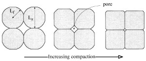
Pressure solution reduces porosity by compaction and cementation as the dissolved material is deposited at pore space nearby or somewhere else (Groshong, 1988). For an idealized rock made up of arrays of nearly spherical grains shown in Figure 1 (Renard et al., 1999), pressure solution will truncate the grains at their contacts and fill the pore space around the grains and reduce the porosity (Sprunt and Nur, 1976). This process is called chemical compaction. In open systems, dissolved material may be carried by the circulating fluid for a long distance, even to another formation, before being re-deposited. In closed systems, on the other hand, dissolved materials may tend to be re-deposited nearby due to limited formation fluid mobility.

A cross-section view of a cubic-packed network of truncated spheres. The grain shapes evolve due to pressure solution as shown: the grain radius Lf increases while the grain flattens (Lz decreases) resulting in the porosity and the pore surface decrease. From Renard et al (1999).Figure 1. A cross-section view of a cubic-packed network of truncated spheres. The grain shapes evolve due to pressure solution as shown: the grain radius Lf increases while the grain flattens (Lz decreases) resulting in the porosity and the pore surface decrease. From Renard et al (1999).

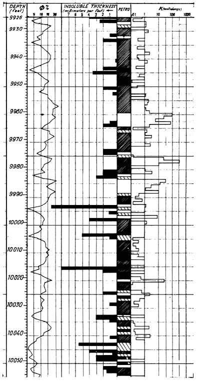
Many investigators proposed porosity changes associated with pressure solution seams and the resulting lower permeability than their host rock (Nelson, 1981; Koepnick, 1984; Tremolieres, 1984). However, the nature of this change is not simple. Braithwaite (1988) proposed that some stylolites were conduits for fluid.

Experimental results indicated that a single seam may affect a zone from 0.5 feet (Wong and Oldershaw, 1981) to about 5 feet (Dunnington, 1967) in width to either side. Tremolieres (1984) presented log data showing lower porosity in zones with high concentration of pressure solution seams (Figure 2) from a Cretaceous carbonate reservoir, Abu Dhabi, United Arab Emirates.

Representative porosity, stylolite, and lithology log from the crest of the reservoir structure. From Tremolieres (1984).Figure 2. Representative porosity, stylolite, and lithology log from the crest of the reservoir structure. From Tremolieres (1984).

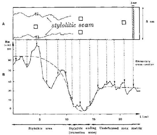
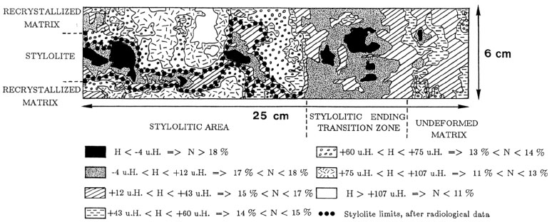
Carrio-Schaffhauser et al. (1990) reported high radiological density (Figure 3 and Figure 4) indicative of fine matrix structure and low porosity, along tectonic pressure solution seams from core samples in Cretaceous limestone from south-eastern France. They also identified low porosity zones at the tips of the seams and interpreted them as a transient phenomenon.

Average radiological density profile: (A) Traces of a single stylolite seam on a core surface. (B) Radiological profile obtained from serial cross-sections. Each point on this curve is given by the average density of one cross-section, expressed in Hounsfield units, Hm. Three main zones appear: the undeformed rock matrix (Hm about +35 u.H.), the stylolitic ending or transition zone (Hm about -10 u.H.), and the stylolite area (Hm reaches +115 u.H). From Carrio-Schaffhauser et al. (1990).Figure 3. Average radiological density profile: (A) Traces of a single stylolite seam on a core surface. (B) Radiological profile obtained from serial cross-sections. Each point on this curve is given by the average density of one cross-section, expressed in Hounsfield units, Hm. Three main zones appear: the undeformed rock matrix (Hm about +35 u.H.), the stylolitic ending or transition zone (Hm about -10 u.H.), and the stylolite area (Hm reaches +115 u.H). From Carrio-Schaffhauser et al. (1990).
Radiological map drawn on computerized reconstructed cross-sections obtained on the sample and normal to the plane shown in the previous figure. Three main zones were found, with the stylolitic area divided into two parts: the stylolite s.s., made up of insoluble residue concentrations and, on either side, part of the rock subjected to dissolution processes; the host recrystallized matrix. From Carrio-Schaffhauser et al (1990).Figure 4. Radiological map drawn on computerized reconstructed cross-sections obtained on the sample and normal to the plane shown in the previous figure. Three main zones were found, with the stylolitic area divided into two parts: the stylolite s.s., made up of insoluble residue concentrations and, on either side, part of the rock subjected to dissolution processes; the host recrystallized matrix. From Carrio-Schaffhauser et al (1990).

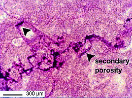
Guilhaumon et al. (2004) documented secondary porosity change (Figure 5) within the flat parts of stylolites in limestone from Pakistan.

Photomicrography of bioclastic carbonate wackestone with tectonic stylolites, in transmitted light showing the porosity of stylolite cap (black arrow). From Guilhaumou et al. (2004).Figure 5. Photomicrography of bioclastic carbonate wackestone with tectonic stylolites, in transmitted light showing the porosity of stylolite cap (black arrow). From Guilhaumou et al. (2004).

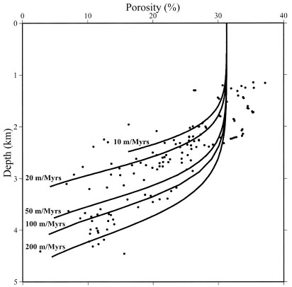
It is well known that porosity may decrease with depth in sedimentary basins as a result of compaction and pressure solution. Renard et al. (1999) compared their model with data from sandstone of Norwegian margin (Ramm, 1992) and showed that the porosity generally decreases with depth as shown in Figure 6. Within the first 2 km, mechanical compaction dominates and compaction due to pressure solution is very slow because the temperature is low and quartz kinetics are very slow. The curves in Figure 6 represent the amount of compaction induced by pressure solution. The curves do not represent porosity variations above 2 km. Below 2 km, both the numerical curves and the field data show the trend that porosity continually decreases with depth. If the dissolved silica forms quartz cementation around grains close by, the strength of the sandstone is increased along with decreased porosity. Safaricz and Davison (2005) reported significant reductions in porosity associated with pressure solution seams in chalk from the North Sea. The initial porosity ranges from 70% to 80%. In the first tens to hundreds of meters of burial, porosity is then reduced to 38% to 48% by mechanical compaction. Continued burial leads to further diagenesis by extensive pressure solution, reducing the porosity to 15% to 30% at 1500 to 2000 m depth and to 2% to 25% at 2700 to 3300 m depth.

Porosity–depth relationships in a sandstone. Dots represent data in sandstones from the Norwegian shelf (Ramm, 1992). The curves are porosity–depth relationships calculated with a model by Renard et al (1999) of pressure solution for different sedimentation rates. In the numerical model, a constant rate of sedimentation is assumed. Grain size, fluid pressure, and temperature gradient (35ºC=km) are similar to that in the Norwegian shelf. Between 0 and 2 km, pressure solution is inefficient and its efficiency increases rapidly at around 3 km. From Renard et al. (1999).Figure 6. Porosity–depth relationships in a sandstone. Dots represent data in sandstones from the Norwegian shelf (Ramm, 1992). The curves are porosity–depth relationships calculated with a model by Renard et al (1999) of pressure solution for different sedimentation rates. In the numerical model, a constant rate of sedimentation is assumed. Grain size, fluid pressure, and temperature gradient (35ºC=km) are similar to that in the Norwegian shelf. Between 0 and 2 km, pressure solution is inefficient and its efficiency increases rapidly at around 3 km. From Renard et al. (1999).

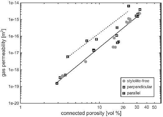
Pressure solution seams, especially when they are thick and continuous can cause reservoir compartmentalization and channeled fluid flow parallel to them. Dunnington (1967) reported stylolites in carbonate reservoirs in Iraq trapping oil. Wall et al. (2006) supported this by showing the lack of bitumen in unsheared pressure solution seams, in contrast to the presence of bitumen in a connected network of other fractures. A recent study by Heap et al. (2014) concluded that the stylolites that they studied in the laboratory result in lower permeability in a direction normal to them (Figure 7). However, they also suggested that the stylolites are made up of short discontinuous components and therefore they may not impact regional fluid flow. It appears that the reported influences of pressure solutions on fluid flow show significant variations and care should be taken in evaluating each situation case by case.

Permeability and connected porosity of stylolites in limestone, which were measured in the laboratory using 2 MPa confining pressure. The solid line corresponds to the power law fit to the stylolite-free and stylolite-perpendicular flow. The dashed line represents the power law fit to the data from stylolite parallel flow. From Heap et al. (2014).Figure 7. Permeability and connected porosity of stylolites in limestone, which were measured in the laboratory using 2 MPa confining pressure. The solid line corresponds to the power law fit to the stylolite-free and stylolite-perpendicular flow. The dashed line represents the power law fit to the data from stylolite parallel flow. From Heap et al. (2014).
Reference:

Braithwaite, C.J.R., 1988. Stylolites as open fluid conduits. Marine and Petroleum Geology 6: 93-96.

Carrio-Schaffhauser, E., Raynaud, S., Latière, Mazerolle, F., 1990. Propagation and localization of stylolites in limestones. Geological Society, London, Special Publications 54: 193-199.

Dunnington, H.V., 1967. Aspects of diagrnesis and shape change in stylolitic limestone reservoirs. World Petroleum Congress, 7th, Mexico, Proceedings 2: 339-352.

Groshong, R.H., Jr, 1988. Low-temperature deformation mechanisms and their interpretation. Geological Society of America Bulletin 100: 1329-2360.

Guilhaumou, N., Benchilla, L., Mougin, P., Dumas, P., 2004. Advances in hydrocarbon fluid-inclusion microanalysis and pressure-volume-temperature modeling:Diagenetic history, pressure-temperature, and fluid-flow Reconstruction—A Case Study in the North Potwar Basin, Pakistan. in R. Swennen, F. Roure, and J. W. Granath, eds., Deformation, fluid flow, and reservoir appraisal in foreland fold and thrust belts: American Association of Petroleum Geologists Hedberg Series, no.1, 5– 20.

Heap, M.J., Baud, P., Reuschle, T., Meredith, P., 2014. Stylolites in limestones: Barriers to fluid flow. Geology 42: 51-54, doi:10.1130/G34900.1.

Koepnick, R.B., 1984. Distribution and vertical permeability of stylolites within a lower cretaceous carbonate reservoir, Abu Dhabi, United Arab Emirates. In Stylolites and Associated Phenomena - Relevance to Hydrocarbon Reservoirs, Yahya, F. A. (ed.), Special Publ., Abu Dhabi National Reservoir Research Foundation, 261-278.

Nelson, R.A., 1981. Significance of fracture sets associated with stylolite zones. American Association of Petroleum Geologists Bulletin 65:2417-2425.

Ramm, M., 1992. Porosity depth trends in reservoir sandstones - theoretical-models related to Jurassic sandstones offshore Norway. Marine and Petroleum Geology 9 (5): 553-567.

Renard, F., Ortoleva, P., Gratier, J.P., 1999. An integrated model for transitional pressure solution in sandstones. Tectonophysics 312 (2-4): 97-115.

Safaricz, M., Davison, I., 2005. Pressure solution in chalk. American Association of Petroleum Geologists Bulletin 89 (3): 383-401.

Sprunt, E.S., Nur, A., 1976. The reduction of porosity by pressure solution: Experimental verification. Geology 4: 463-466.

Tremolieres, P., 1984. Stylolites of tectonic origin measurements of volume reduction and destructional effects on reservoir properties. In Stylolites and Associated Phenomena - Relevance to Hydrocarbon Reservoirs, Yahya, F. A. (ed.), Special Publ., Abu Dhabi National Reservoir Research Foundation, 237-245.

Wall, B.R.G., Girbacea, R., Mesonjesi, A., Aydin, A., 2006. Evolution of fracture and fault-controlled fluid pathways in carbonates of the Albanides fold-thrust belt. American Association of Petroleum Geologists Bulletin 90 (8): 1227-1249.

Wong, P.D., Oldershaw, A., 1981. Burial cemmentation in the Devonian, Kaybob Reef Complex, Alberta, Canada. Journal of Sedimentary Petrology 97: 507-520.


Readme    |    About Us    |    Acknowledgement    |    How to Cite    |    Terms of Use    |    Ⓒ Rock Fracture Knowledgebase