| |||||||||
|
|
|||||||||
|
|
|||||||||
| Mechanisms and Mechanics of Multiple Thrust Fault Sets | |||||||||
|
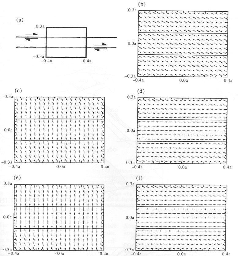
The simplest conceptual model for crustal scale thrust fault systems generally includes one primary set of thrust faults localized in horizontal or low-angle weak stratigraphic units (Boyer and Elliott in early 1980s and Suppe, 1985; and his co-workers, Dahlen et al., 1984). The latter is based on a faulting mechanisms and named the critical wedge theory to analyze primarily foreland-directed thrusting in terms of the strength of sedimentary rocks. Suppe (1985) also proposed thrust fault-related folding illustrated in other categories in this Knowledgebase. An outcrop-scale study by Ohlmacher and Aydin (1997) employed a displacement discontinuity method to calculate the stress distribution associated with sub-parallel horizontal or low-angle slip planes shown in Figure 1(a). The diagrams in (b) through (f) summarize the maximum and minimum principal stress orientations as a function of the friction coefficients along the shear fractures and the orientation of the driving stresses. The conclusions were that the orientation of the maximum and minimum principal stresses vary from oblique to the shear fracture (b), to high-angle (c and e), and sub-parallel to the shear fractures (d and f).
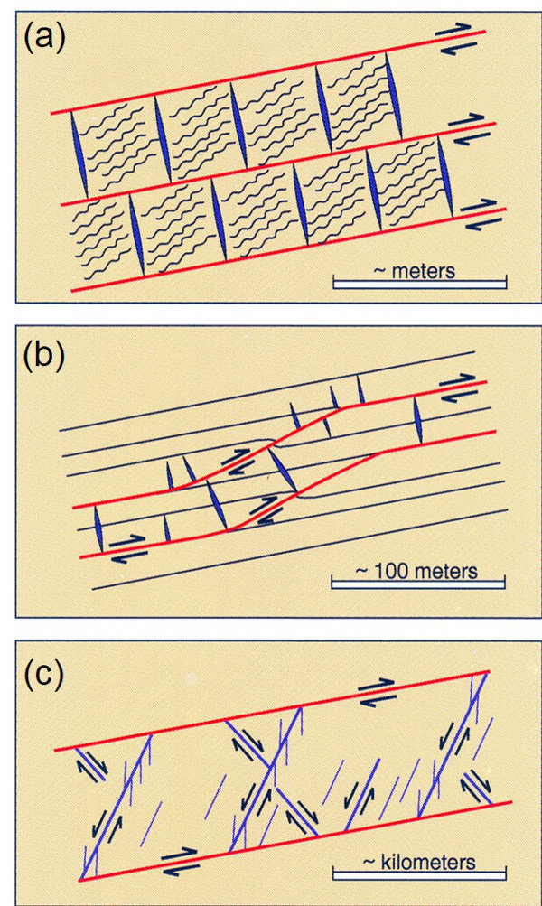
Figure 2(a) shows a set of thrust faults along bedding planes or weak lithologies and small scale discontinuities such as veins and pressure solutions between them. 2(b) envisions these thrust faults cutting up-section to increase their length and 2(c) depicts larger scale interaction between sub-parallel large thrust faults and shear planes between them. Other related data and concepts are provided under 'Multiple Thrust Fault Sets.'
| |||||||||
| Reference: |
|||||||||
| Boyer, S.E., Elliot, D., 1982 Dahlen, F.A., Suppe, J., Davis, D.M., 1984 Ohlmacher, G., Aydin, A., 1997 Suppe, J., 1985 |
|||||||||
|
Readme | About Us | Acknowledgement | How to Cite | Terms of Use | Ⓒ Rock Fracture Knowledgebase |
|||||||||