|
Schematic 2-D (Figure 1) and 3-D (Figure 2) diagrams illustrate the geometry of pressure solution seams (stylolites). Individual seams, or seam segments form islands, together can be considered a composite structure. Additional examples of somewhat similar configurations can be found in detailed descriptions of pressure solution seams and their zones. In fact, any pressure solution seam identified visually by the naked eye is made up of numerous short and discontinuous interrelated segments in high magnification and may be considered as a composite structure. Please see 'Components of Pressure Solution Seams' and 'Pressure Solution Seam Zones' for the images and their descriptions.
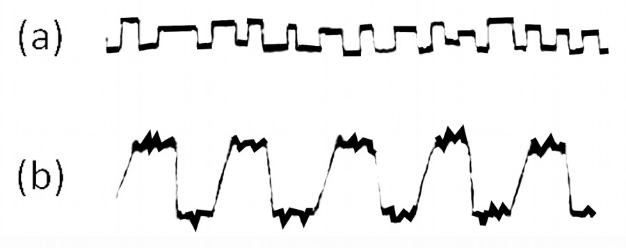
 | | Figure 1. 2-D schematic representation of columnar, sharp-edged pressure solution seams (stylolites). Slightly modified (to show isolated islands of residue) from Guzzetta (1984). |
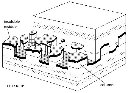
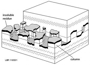 | | Figure 2. 3-D schematic diagram of a series of islands of pressure solution seams forming what would be considered composite seams or stylolites. From L. B. Railsback's web site at http://www.gly.uga.edu/railsback/, modified from John V. Smith (2000). |
| |