Rock Fracture
KNOWLEDGEBASE
  

Fractures in Waterpocket Monocline, UT, USA

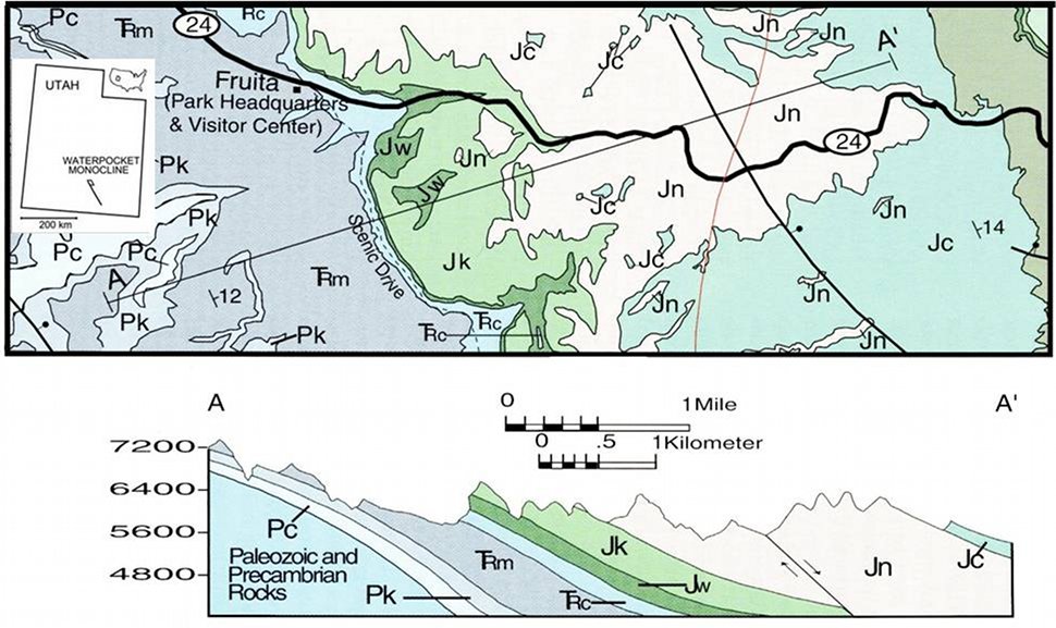
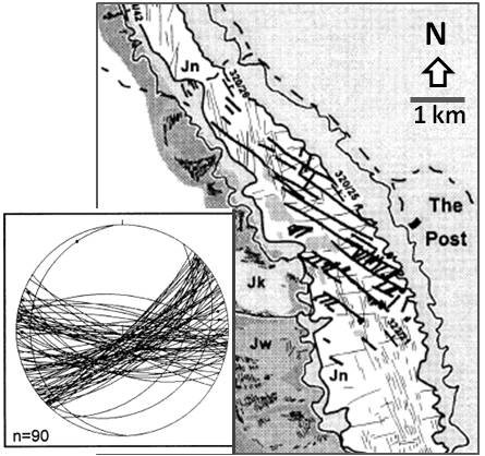
The Waterpocket fold is one of many basement involved Laramide structures of upper Cretaceous to Eocene age which occur throughout the Colorado Plateau. It is a N-S trending monoclinal flexure of about 100 miles long in south-central Utah (Figure 1 and Figure 2). Similar to many other monoclines of the Colorado Plateau, it is attributed to sedimentary cover response to a high-angle basement fault of probably reverse kind (Morris et al., 2000). The core of the monocline occurs primarily in the Jurassic sandstones known as the Glen Canyon Group which includes from oldest to youngest the Wingate, Kayenta, and Navajo (Figures 1 and 2). The older two are primarily fluvial and the youngest is typically an aeolian deposit.

Air photo map along the Waterpocket monocline from the Grand Wash (about 5 km south of Utah Highway 24 to south of the Sheets Gulch showing various structures (light lines for joints thick black lines for shear band faults) and their measured orientations (the inset stereonet plot). From Roznovsky and Aydin (2001).Figure 1. Air photo map along the Waterpocket monocline from the Grand Wash (about 5 km south of Utah Highway 24 to south of the Sheets Gulch showing various structures (light lines for joints thick black lines for shear band faults) and their measured orientations (the inset stereonet plot). From Roznovsky and Aydin (2001).
Strip map and cross section across the Waterpocket monocline in northern Capitol Reef National Park, Utah. Slighly changed from Morris et al. (2000).Figure 2. Strip map and cross section across the Waterpocket monocline in northern Capitol Reef National Park, Utah. Slighly changed from Morris et al. (2000).

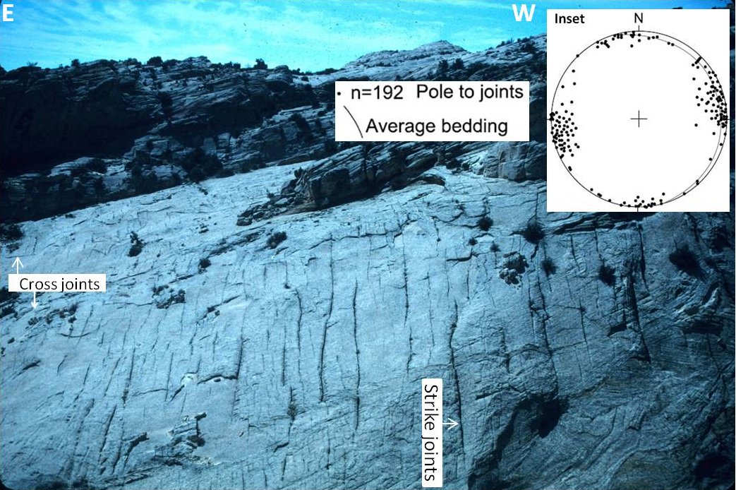
Aside from the main monoclinal flexure in the sedimentary cover, there is a wide variety of structures including faults, joints and deformation bands exposed along and across the fold (Davis, 1999; Roznovsky and Aydin, 2001; Davatzas and Aydin, 2003). The previous studies have documented joints dominated by the monocline-axis parallel or along-strike set (Figure 3) though joint sets in other orientations are also present. Faults are also common along and across the monocline. We here distinguish between two different types of faults: deformation band or more precisely shear band type and those developed from shearing of primarily the monocline parallel joints. We also note local bedding plane faults and related splay fractures.

A well-developed set of joints trending parallel to the monocline axial plane in the Navajo Sandstone cropping out northern Capitol Reef National Park, south of Utah Highway 24.Figure 3. A well-developed set of joints trending parallel to the monocline axial plane in the Navajo Sandstone cropping out northern Capitol Reef National Park, south of Utah Highway 24.

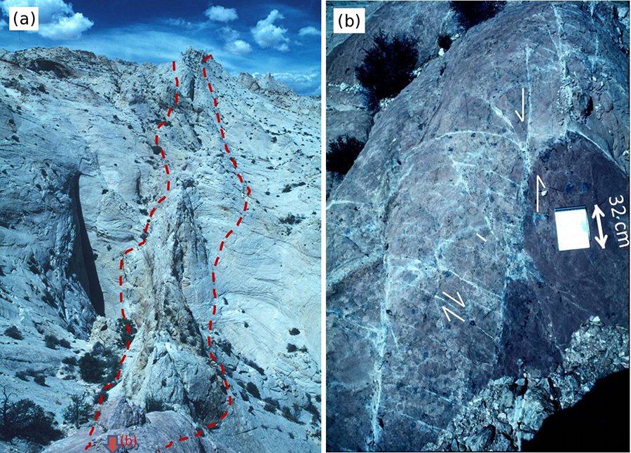
The shear band type faults such as that in Figure 4a are more common in the Navajo Sandstone. Figure 4(a) shows tpical high-relief of the shear band faults (Aydin and Johnson, 1978; Davis, 1999) and Figure 4(b) which is an annotated photo (bird's eye view) of an area at the south end of the image of the same fault zone with a Riedel type ladder structure (Davis, 1999; Katz et al., 2004) composed of a dominant left-lateral offset along the northerly trending set and a right-lateral offset along the northwesterly trending set. Notice that the red unit close to the viewer in the lower right corner is offset left-laterally for larger than 2 meters.

(a) A shear band fault zone and its damage zone (highlighted with dash-lines) in the Navajo sandstone in the Sheets Gulch area. The zone has about 16 meters relief and several meters left-lateral offset. (b) A bird's eye view of a nearly flat surface at the southern end of the shear band fault zone in (a) showing shear bands in Riedel configuration with left- and right -lateral offsets (marked by arrows). Note that the reddish unit on the lower left of the view is offset by a series of shear band faults for at least 2 meters in a left lateral sense.Figure 4. (a) A shear band fault zone and its damage zone (highlighted with dash-lines) in the Navajo sandstone in the Sheets Gulch area. The zone has about 16 meters relief and several meters left-lateral offset. (b) A bird's eye view of a nearly flat surface at the southern end of the shear band fault zone in (a) showing shear bands in Riedel configuration with left- and right -lateral offsets (marked by arrows). Note that the reddish unit on the lower left of the view is offset by a series of shear band faults for at least 2 meters in a left lateral sense.

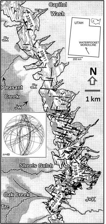
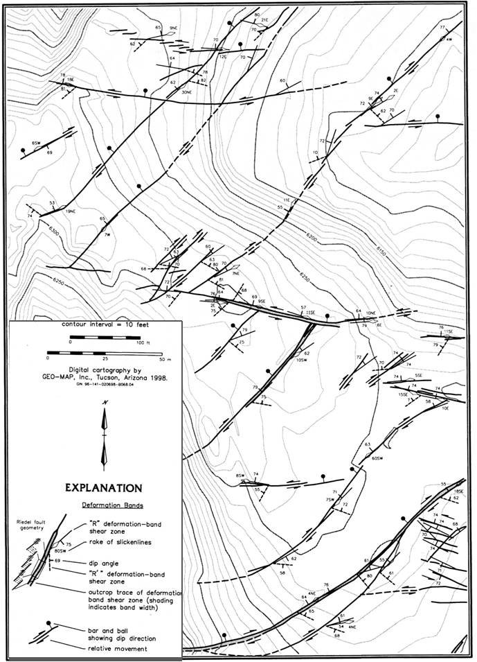
Figure 5 is a highly accurate map of the Sheets Gulch area by George Davis and his students showing the pattern and other attributes of such a system in the Sheets Gulch area along the monocline. The pattern appears to be conjugate with the acute intersection angle between the left-lateral and right-lateral sets pointing in the direction approximately perpendicular to the monocline axis. The faults are generally of strike-slip but dip-slip components are also present. As will be pointed in the mechanisms and mechanics section, there is a strong correlation between the concentration of the shear band faults and the complexities along the monocline geometry as indicated by Figure 6.

Detailed map of the Sheets Gulch area showing two sets of shear band faults with left- and right- lateral offsets in conjugate pattern. Normal sense of slip indicated by bars is also present. From Davis (1999).Figure 5. Detailed map of the Sheets Gulch area showing two sets of shear band faults with left- and right- lateral offsets in conjugate pattern. Normal sense of slip indicated by bars is also present. From Davis (1999).
Airphoto map of a select area at the Post area (about 25 km south of the Sheets Gulch) showing shear band faults concentration at a bend along the monocline. Steronet shows the measured orientation of the shear bands. From Roznovsky and Aydin (2001).Figure 6. Airphoto map of a select area at the Post area (about 25 km south of the Sheets Gulch) showing shear band faults concentration at a bend along the monocline. Steronet shows the measured orientation of the shear bands. From Roznovsky and Aydin (2001).

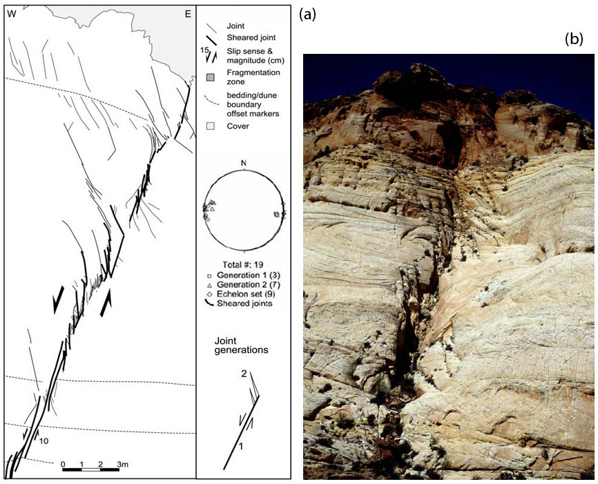
The other type of faults developed from successive shearing of joints, predominantly parallel to the axis of the monocline, splay fracturing, and shearing of the splay fractures. These faults are of normal sense and have an apparent conjugate pattern but the acute angle between the two complementary sets point the vertical direction. By examining field cases of incipient, moderate, and well-developed faults particularly in cross-sections, the temporal and spatial evolution of the hierarchical faults developed this way can be elucidated. At the incipient stage of faulting (Figure 7), which accommodates slip from millimeters to centimeters, faults are composed of two structural elements: sheared joints and splay joints (Davatzes and Aydin, 2003) . Sheared joints were initial joints which reactivated in shearing, with traces paralleling to those of monocline-parallel joints observed throughout the park. Splay joints abut at an oblique angle (kink angle) against the sheared joints and typically occur at or near the tips of the sheared joints. Even at this incipient stage, it is possible to detect minute amount of shearing across some of the splay joints (see those at the central part of the fault).

Map (a) and photograph (b) of an outcrop showing the cross section of an incipient fault in the Wingate Sandstone at the Waterpocket monocline. Cartoon at the lower right corner of (a) summarizes the relative ages of fault components infered from crosscutting relationships. From Davatzes and Aydin (2003).Figure 7. Map (a) and photograph (b) of an outcrop showing the cross section of an incipient fault in the Wingate Sandstone at the Waterpocket monocline. Cartoon at the lower right corner of (a) summarizes the relative ages of fault components infered from crosscutting relationships. From Davatzes and Aydin (2003).

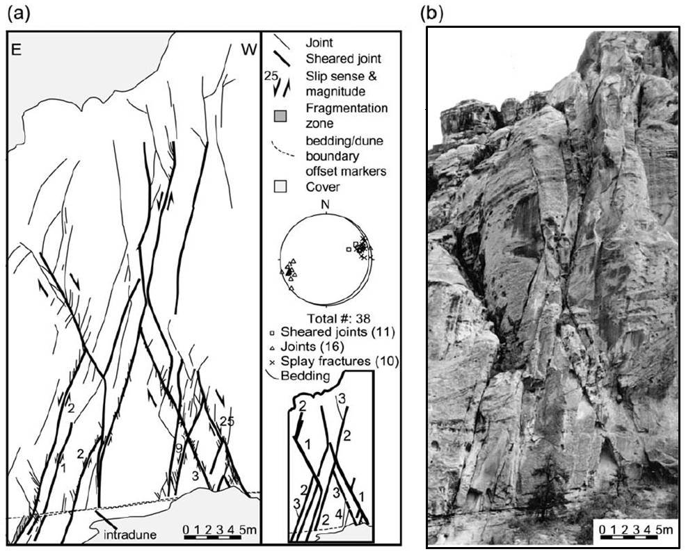
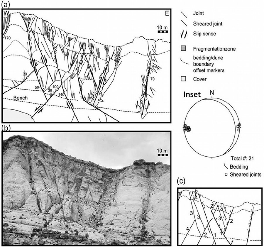
Moderately developed fault systems (Figure 8) are characterized by an 'apparent' conjugate fault pattern, which is composite of two sets of faults with opposite dip (see discussion under the Apparent Conjugate Pattern). The mature faults occur in zones with tens of meters wide and have cumulative offset of a few meters. In this particular example, four generations of joints or sheared joints are observed (see the annotated drawing in the lower corner of Figure 8). In all cases, younger sets of joints have smaller offsets than older ones. Individual sheared joints in the older generations have up to about 25 cm offset, while those of the 4th generation fractures are just splays and lack shear offset.

Map (a) and photo (b) of an outcrop showing cross section of a moderate-developed fault in Wingate Sandstone, the Waterpocket monocline. Cartoon at the lower right corner of (a) summarizes the relative ages of fault components inferred from crosscutting relationships. From Davatzes and Aydin (2003).Figure 8. Map (a) and photo (b) of an outcrop showing cross section of a moderate-developed fault in Wingate Sandstone, the Waterpocket monocline. Cartoon at the lower right corner of (a) summarizes the relative ages of fault components inferred from crosscutting relationships. From Davatzes and Aydin (2003).

Well-developed fault zones, such as that shown in Figure 9, has a zone, the width of which reaching about 120 meters and cumulative offset of several meters.

Map (a) and photo (b) of an outcrop showing the cross section of a well-developed fault system in Navajo Sandstone at the Waterpocket monocline. The offset labeled in (a) is in centimeters, the largest one is 170 cm. Enlarge to see detail. Cartoon (c) summarizes the age relationships between different structural components of the fault system. From Davatzes and Aydin (2003). Figure 9. Map (a) and photo (b) of an outcrop showing the cross section of a well-developed fault system in Navajo Sandstone at the Waterpocket monocline. The offset labeled in (a) is in centimeters, the largest one is 170 cm. Enlarge to see detail. Cartoon (c) summarizes the age relationships between different structural components of the fault system. From Davatzes and Aydin (2003).

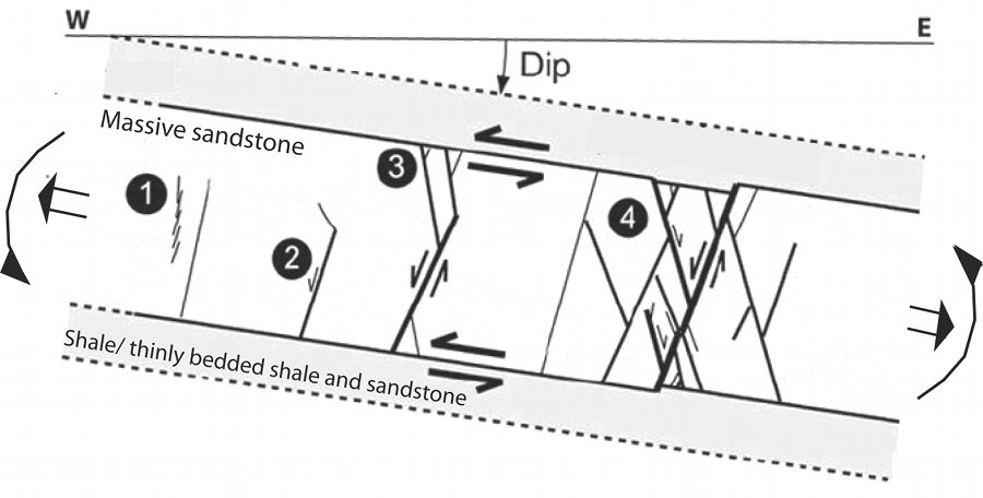
Figure 10 shows a conceptual diagram showing deformation of a sandstone-shale sequence representing the Glen Canyon group in the Capitol Reef area by bending and extension of massive sandstone formations due to an underlying high-angle dip-slip fault. It is possible to find evidence for bed-parallel faults located along the sandstone -shale (or thinly bedded sandstone and shale) units. Following the deformation by shear band faults, the younger generation of faulting occurs by shearing of monocline axis-parallel joints (1 to 4 in the diagram). This age relationship can be deduced from the joint sets and the sheared joint-based faults cutting across the shear band faults as shown by the photo in joints-deformation bands assemblage section; Back to the conceptual diagram in Figure 10, (1) represents jointing, (2) shows the splay fracturing, and (3) and (4) depict the development of two sets of normal faults with an apparent conjugate pattern. It is possible that bending and tilting of the beds in response to incremental movement across the underlying faults provides the mechanism for sequential shearing of the multiple generation of fractures.

Conceptual model for deformation mechanism of the Mesozoic sandstone-shale sequence in the Waterpocket monocline (Utah) with a focus on the initiation and development of the monocline axis-parallel normal faults. Massisve sandstone units subjected to bending and extension and bed-parallel slip initially fractured (1), then these fractures were subjected to normal sense of shearing (2). Eventually, splay fracturing and shearing of the splay fractures results in apparent conjugate normal fault patterns. Slightly changed from Davatzas and Aydin (2003).Figure 10. Conceptual model for deformation mechanism of the Mesozoic sandstone-shale sequence in the Waterpocket monocline (Utah) with a focus on the initiation and development of the monocline axis-parallel normal faults. Massisve sandstone units subjected to bending and extension and bed-parallel slip initially fractured (1), then these fractures were subjected to normal sense of shearing (2). Eventually, splay fracturing and shearing of the splay fractures results in apparent conjugate normal fault patterns. Slightly changed from Davatzas and Aydin (2003).
Reference:

Aydin, A., Johnson, A.M., 1978. Development of faults as zones of deformation bands and as slip surfaces in sandstone. Pure and Applied Geophysics 116: 931–942.

Davatzes, N.C., 2003. Fault architecture as a function of deformation mechanism in clastic rocks with an emphasis on sandstone. PhD Dissertation, Stanford University.

Davatzes, N.C., Aydin, A., 2003. The formation of conjugate normal fault systems in folded sandstone by sequential jointing and shearing, Waterpocket monocline, Utah. Journal of Geophysical Research 108 (B10): Art. No. 2478.

Davis, G.H., 1999. Structural Geology of the Colorado Plateau region of Southern Utah with special emphasis on deformation bands. Geological Society of America Special Paper 342, 157p.

Katz, Y., Weinberger, R., Aydin, A., 2004. Geometry and kinematic evolution of Riedel shear structures, Capitol Reef National Park, Utah. Journal of Structural Geology 26: 491–501.

Morris, T.H., Manning, V.W., Ritter, S.M., 2000. Geology of Capitol Reef National Park, Utah, 85 - 105. In, Sprinkel, D.A., Chidsey, Jr., T.C., Anderson, P.B., Editors, Geology of Utah's National Parks and Monuments. Utah Geological Association Publication 28, Salt Lake City.

Roznovsky, T., Aydin, A., 2001. Concentration of shearing deformation related to changes in strike of monoclinal fold axis: The Waterpocket Monocline, Utah. Journal of Structural Geology 23: 1567-1579.


Readme    |    About Us    |    Acknowledgement    |    How to Cite    |    Terms of Use    |    Ⓒ Rock Fracture Knowledgebase