Rock Fracture
KNOWLEDGEBASE
  

Mechanisms and Mechanics of Non-orthogonal Systems

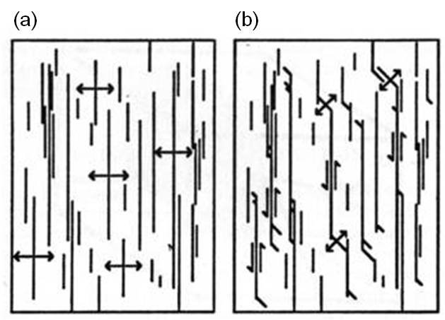
Using the definition that joints form along the principal planes perpendicular to the greatest tension or the least compression (Figure 1a), non-orthogonal joint sets represent different stress states. It follows that the older set (the first set) must have been subjected to some shearing as depicted in the schematic diagram in Figure 1b.

(a) and (b) An initial joint set and a later joint set formed through splay fracturing by shearing of the first set. From Pollard and Aydin (1988). (c) and (d) Schematic diagrams showing the two stress states which require the rotation of the remote stresses. From Gonzales and Aydin (2008).Figure 1. (a) and (b) An initial joint set and a later joint set formed through splay fracturing by shearing of the first set. From Pollard and Aydin (1988). (c) and (d) Schematic diagrams showing the two stress states which require the rotation of the remote stresses. From Gonzales and Aydin (2008).

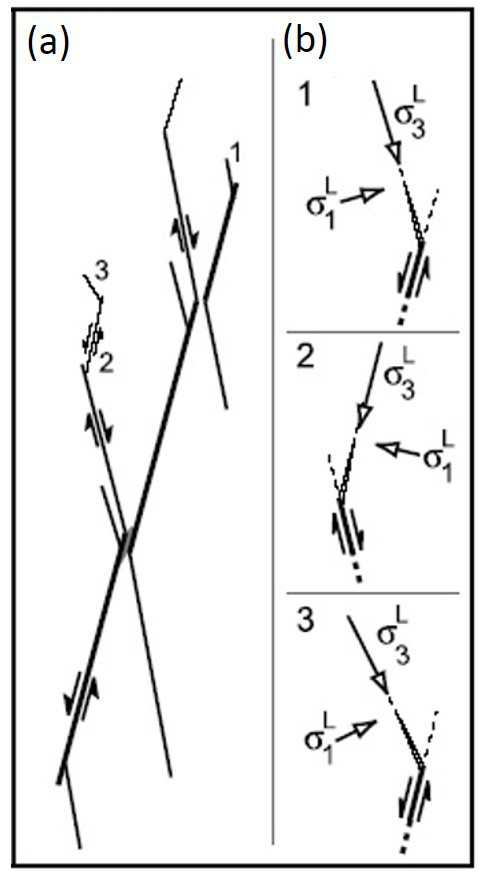
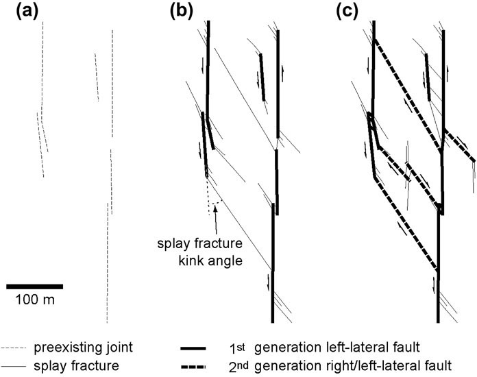
Sometimes the so-called splay joints (the second set) are subsequently sheared also forming another set of splay joints (third set) which may or may not be in the orientation of the first set. These have been documented in great detail in various kinds of faulting environments as illustrated in Figure 2 and Figure 3 (Davatzes and Aydin, 2003; Myers and Aydin, 2004; Flodin and Aydin, 2004).

(a) Sequential shearing in a normal sense of an initial discontinuity and the subsequent splays. Numbers indicate the order of formation. (b) Rotation of local stresses as inferred from the splay orientation. From Davatzes and Aydin (2003).Figure 2. (a) Sequential shearing in a normal sense of an initial discontinuity and the subsequent splays. Numbers indicate the order of formation. (b) Rotation of local stresses as inferred from the splay orientation. From Davatzes and Aydin (2003).
A series of diagrams illustrating the formation of multi-generations of strike-slip faults by shearing of initial joints or joint zones in a left-lateral sense (a) and the formation of splays (b) which are consequently sheared in a right-lateral sense. The final product is a hierarchical set of left- and right-lateral faults. Rearranged from Flodin and Aydin (2004).Figure 3. A series of diagrams illustrating the formation of multi-generations of strike-slip faults by shearing of initial joints or joint zones in a left-lateral sense (a) and the formation of splays (b) which are consequently sheared in a right-lateral sense. The final product is a hierarchical set of left- and right-lateral faults. Rearranged from Flodin and Aydin (2004).

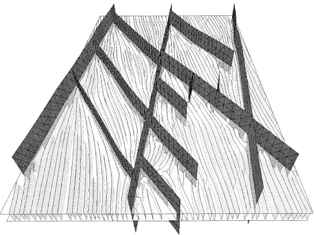
It turns out that the underlying basic mechanism of this process is the formation of splay joints by shearing of an initial flaw including a joint or a joint set. Please see 'Mechanisms and Mechanics of Splay Joints' for more details. Rawnsley et al. (1992; 1997), Bourne and Williams (2001), Kattenhorn et al. (2000), and Maerten et al. (2006) have simulated joint formations associated with faults in an elastic stress field. Figure 4 shows a 3D pattern of a joint network induced by local stresses associated with a system of strike-slip faults at Bristol Channel (UK). The basic premise is that the joints in an elastic stress field around a network of strike-slip faults propagate along the principal stress trajectory corresponding to that perpendicular to the greatest tension or the least compression. Here, more complex joint patterns occur near the intersections of the faults. It is also clear that the shorter faults between continuous systematic sets occur in a splay orientation with respect to the latter (see de Joussineau et al., 2007 for the so-called kink-angle distribution) suggesting that they formed as splay joints prior to their shearing.

Three-dimensional modeling of faults and related joints present at the Nash Point outcrop. Tensile fracture growth has been simulated in an elastic stress field around the faults. Here more complex joint patterns occur near the intersections of the faults suggesting that most joints formed after the fault initiation. From Bourne and Willimse (2001).Figure 4. Three-dimensional modeling of faults and related joints present at the Nash Point outcrop. Tensile fracture growth has been simulated in an elastic stress field around the faults. Here more complex joint patterns occur near the intersections of the faults suggesting that most joints formed after the fault initiation. From Bourne and Willimse (2001).
Reference:

Bourne, S.J., Willemse, E.J.M, 2001. Elastic stress control on the pattern of tensile fracturing around a small fault network at Nash Point, UK. Journal of Structural Geology 23: 1753-1770.

Davatzes, N.C., Aydin, A., 2003. The formation of conjugate normal fault systems in folded sandstone by sequential jointing and shearing, Waterpocket monocline, Utah. Journal of Geophysical Research 108 (B10): Art. No. 2478.

de Joussineau, G., Mutlu, O., Aydin, A., Pollard, D.D., 2007. Characterization of strike-slip fault - splay relationships in sandstone. Journal of Structural Geology 29: 1831-1842, doi:10.1016/j.jsg.2007.08.006.

Flodin, E.A., Aydin, A., 2004. Evolution of a strike-slip fault network, Valley of Fire State Park, southern Nevada. Geological Society of America Bulletin 116 (1-2): 42-59.

Kattenhorn, S., Aydin, A., Pollard, D.D., 2000. Joints at high angles to normal fault strike: An explanation using 3-D numerical models of fault-perturbed stress field. Journal of Structural Geology 22: 1-23.

Maerten, L., Gillespie, P.A., Daniel, J.M., 2006. Three-dimensional geomechanical modeling for constraint of seismic fault simulation. American Association of Petroleum Geologists Bulletin 90: 1337-1358.

Myers, R., Aydin, A., 2004. The evolution of faults formed by shearing across joint zones in sandstone. Journal of Structural Geology 26 (5): 947-966.

Rawnsley, K.D., Rives, T., Hencher, S.R., Lumsden, A.C., 1992. Joint development in perturbed stress fields near faults. Journal of Structural Geology 14: 939-951.

Rawnsley, K.D., Auzias, V., Petit, J.P., Rives, T., 1997. Extrapolating fracture orientations from horizontal wells using stress trajectory models. Petroleum Geoscience 3: 145-152.


Readme    |    About Us    |    Acknowledgement    |    How to Cite    |    Terms of Use    |    Ⓒ Rock Fracture Knowledgebase