Rock Fracture
KNOWLEDGEBASE
  

Mechanisms and Mechanics of Splay Joints

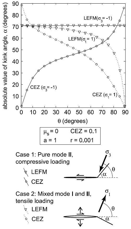
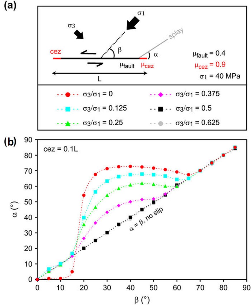
The topic of modeling of splay fracturing is relatively well-studied. Here, we present results from two of these studies: Davatzes and Aydin (2003) and de Joussineau et al. (2007), in part because of the availability of excellent data from both cases. The former is an attempt to rationalize the relationship between a series of well-exposed normal faults and their splays in the Waterpocket monocline in southwestern Utah and the latter is a well-documented splay fractures study associated with numerous strike-slip faults in Valley of Fire State Park, southeastern Nevada. The combination of the resolved shear stress and normal stress components on the initial discontinuities should be favorable enough to promote sliding across the initial discontinuity. In both modeling cases, the circumferential stresses around the tips are calculated numerically at a distance of 0.0001L and 0.0075L, respectively where L denotes length and the elastic parameters are consistent for those of aeolian sandstones.

The classical LEFM model with compressive driving stress regardless of the angle between the stress and the sliding element produces splays with an angle of ~70 degrees, the flat trend in Figure 1a (Cotterell and Rice, 1980). A greater variation of the angle is evident for other cases with tensile driving stress and models with cohesive end zone of 0.1 times length (L or 2a). The former assumes a frictionless fault and the latter assumes friction across the fault 0.4, but across the cohesive end zone about 0.9. Figure 1 and Figure 2 show possible ranges of the angles between the sheared discontinuity and the resulting splays for an isolated normal fault case and an isolated strike-slip fault case, respectively. These results suggest that the magnitude of the largest principal stress driving the shearing and the angle it makes with the initial discontinuity as well as the friction coefficient for the initial discontinuity are crucial parameters for the splay or kink angles as well as their lengths. The predicted splay angles are higher for smaller ratios of the principal stresses and for the increasing angles between the largest compressive principal stresses and the faults. Also, the splay angles are larger for smaller friction coefficient and for closely spaced interacting sub-parallel faults.

Splay or kink angles (alpha) and the angle that the principal stresses make with the sliding surface (beta) for two different models: Linear Elastic Fracture Mechanics (LEFM) and Cohesive End Zone (CEZ) subjected to unit uniaxial compression (-1 MPA) or tension (1 MPA). The LEFM model under compressive loading produces a splay at 70 degrees to the sliding surface regardless of the angle between the applied principal stress and the frictionless surface. The CEZ model with unit compression (-1 MPA) or tension (1 MPA) predicts a large variation of kink or splay angles for a chosen cohesive end zone of one tenth of the length. From Davatzes and Aydin (2003).Figure 1. Splay or kink angles (alpha) and the angle that the principal stresses make with the sliding surface (beta) for two different models: Linear Elastic Fracture Mechanics (LEFM) and Cohesive End Zone (CEZ) subjected to unit uniaxial compression (-1 MPA) or tension (1 MPA). The LEFM model under compressive loading produces a splay at 70 degrees to the sliding surface regardless of the angle between the applied principal stress and the frictionless surface. The CEZ model with unit compression (-1 MPA) or tension (1 MPA) predicts a large variation of kink or splay angles for a chosen cohesive end zone of one tenth of the length. From Davatzes and Aydin (2003).
Models based on a series of loading (a) and cohesive end zone sizes 0.1 of the length (L) of the sliding element (b). The plots show that the ratio of the principal stresses and the angle between the greatest principal stress and the sliding surface play an important role in the kink or splay angle. From de Joussineau et al. (2007).Figure 2. Models based on a series of loading (a) and cohesive end zone sizes 0.1 of the length (L) of the sliding element (b). The plots show that the ratio of the principal stresses and the angle between the greatest principal stress and the sliding surface play an important role in the kink or splay angle. From de Joussineau et al. (2007).

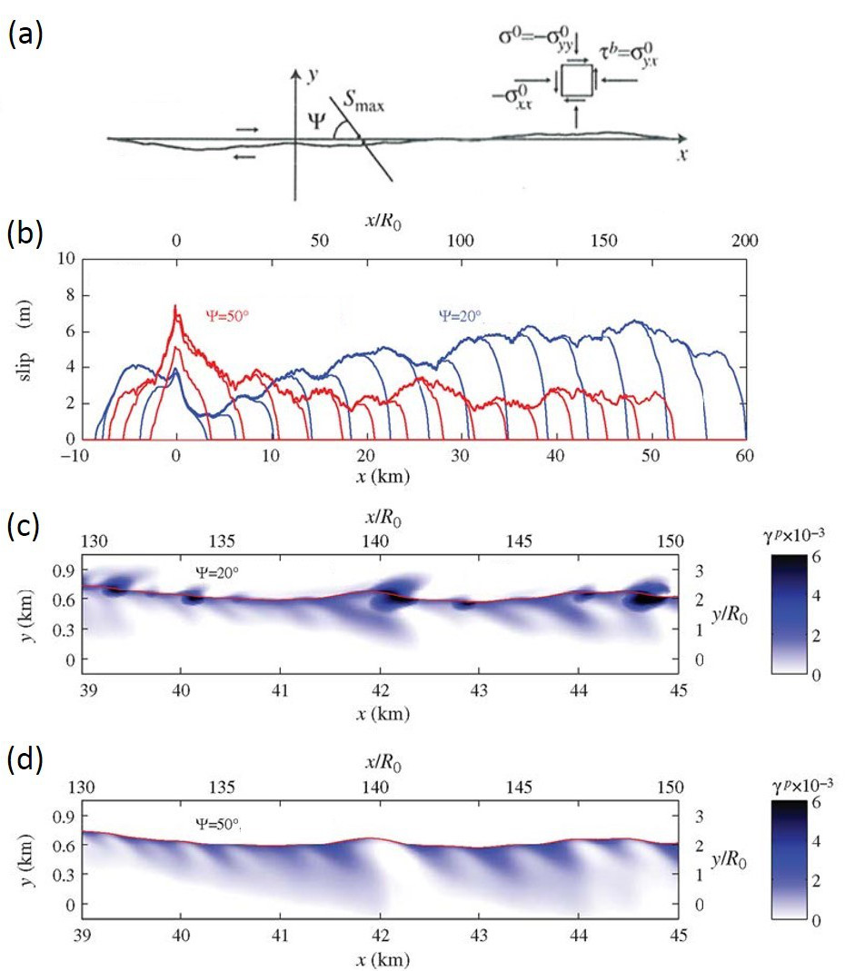
Recent models of plastic strain distribution around super shear faults with high propagation velocity suggest that off-fault deformation may also occur along the faults (Dunham et al., 2011a) particularly around those with rough surfaces (Durham et al., 2011b). Figure 3 illustrates the main results from the latter paper. The authors conclude that the magnitude of plastic strain concentration depends primarily on the propagation velocity and the angle between the maximum principal stress and the average fault orientation.

(a) An idealized strike-slip fault geometry with fractal roughness of the amplitude-to-wavelength ratio of 10-2 in a medium subjected to a background shear stress, τb which is increased to an amount to facilitate fault propagation. (b) Slip profiles in time intervals for the two cases. ψ is the angle between the maximum principal stress, Smax, and x-axis (taken to be 200 and 500 for the two cases in (c) and (d), respectively). R0 is a constant defining the region of strength-drop at the fault rupture front which was assumed to be 300 m. The color bar codes on the right-hand side are the plastic strain. From Dunham et al. (2011b).Figure 3. (a) An idealized strike-slip fault geometry with fractal roughness of the amplitude-to-wavelength ratio of 10-2 in a medium subjected to a background shear stress, τb which is increased to an amount to facilitate fault propagation. (b) Slip profiles in time intervals for the two cases. ψ is the angle between the maximum principal stress, Smax, and x-axis (taken to be 200 and 500 for the two cases in (c) and (d), respectively). R0 is a constant defining the region of strength-drop at the fault rupture front which was assumed to be 300 m. The color bar codes on the right-hand side are the plastic strain. From Dunham et al. (2011b).
Reference:

Cotterell, B., Rice, J.R., 1980. Slightly curved or kinked cracks. Int. J. Fract. 16: 155-169.

Davatzes, N.C., Aydin, A., 2003. The formation of conjugate normal fault systems in folded sandstone by sequential jointing and shearing, Waterpocket monocline, Utah. Journal of Geophysical Research 108 (B10): Art. No. 2478.

de Joussineau, G., Mutlu, O., Aydin, A., Pollard, D.D., 2007. Characterization of strike-slip fault - splay relationships in sandstone. Journal of Structural Geology 29: 1831-1842, doi:10.1016/j.jsg.2007.08.006.

Dunham, E.M., Belanger, D., Cong, L., Kozdon, J.E., 2011a. Earthquake ruptures with strongly rate-weakening friction and off-fault plasticity, Part 1: Planar faults. Bulletin of Seismological Society of America 101: 2296-2307, doi: 10.1785/0120100075.

Dunham, E.M., Belanger, D., Cong, L., Kozdon, J.E., 2011b. Earthquake ruptures with strongly rate-weakening friction and off-fault plasticity, Part 2: Nonplanar faults. Bulletin of Seismological Society of America 101: 2308–2322, doi: 10.1785/0120100076.


Readme    |    About Us    |    Acknowledgement    |    How to Cite    |    Terms of Use    |    Ⓒ Rock Fracture Knowledgebase