Rock Fracture
KNOWLEDGEBASE
  

Mechanisms and Mechanics of Deformation Bands

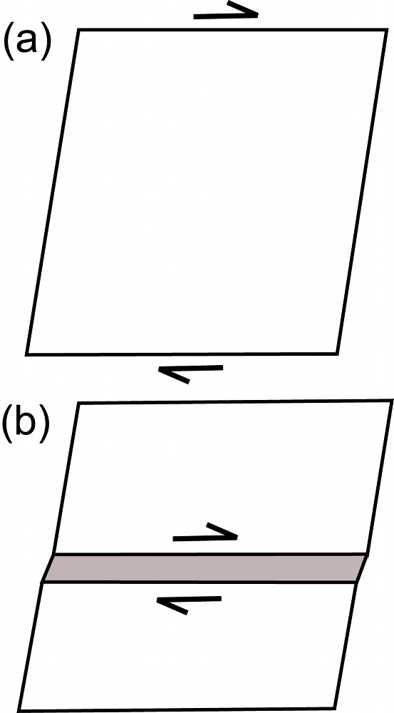
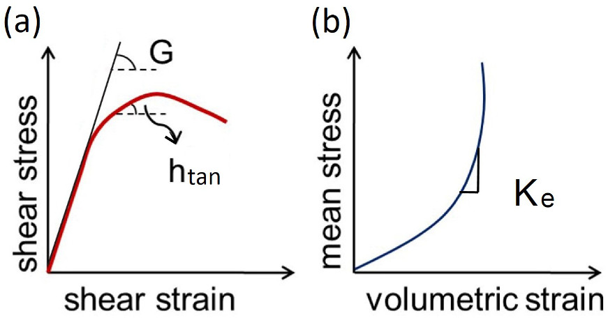
A product of strain localization into a band-like zone whose thickness is much smaller than the other two dimensions is called a deformation band. An instability in homogeneous deformation (Figure 1a) leading to a localized deformation (Figure 1b) is believed to be the mechanism responsible for deformation band initiation. Please see the classical pioneering paper by Rudnicki and Rice (1975). This model is commonly referred to as the bifurcation model and the tangent modulus (htan) and elastic shear modulus (G) as defined in Figure 2a are thought to be important parameters in this process.There exist various kinematics of deformation bands, which will be described in more detail under shear bands and volumetric bands, occurring in a wide variety of materials besides rocks, including metals and alloys (Leach, 1985), aluminum foam (Papka and Kyriakides, 1998), and ice (Aydin, 2006). Although the material properties may vary from one case to another, it has been suggested that a high porosity, greater than approximately 15%, is a prerequisite for deformation band formation in porous granular rocks (Antonellini and Aydin, 1994; and Holcomb et al, 2007). For the volumetric deformation band formation, the effective bulk modulus is also thought to be a critical parameter.

Schematic diagrams showing (a) homogeneous and (b) inhomogeneous deformation. 'Bifurcation' is the term used to describe the transition from an homogeneous deformation to an inhomogeneous deformation with the formation of a deformation band.Figure 1. Schematic diagrams showing (a) homogeneous and (b) inhomogeneous deformation. 'Bifurcation' is the term used to describe the transition from an homogeneous deformation to an inhomogeneous deformation with the formation of a deformation band.
(a) Schematic shear stress-shear strain diagram on which the tangent modulus (htan), a function of hardening modulus (h), and elastic shear modulus (G) are defined. (b) Mean stress-volumetric strain diagram, the slope of which is the effective bulk modulus (Ke). The sign of the volumetric strain indicates volume increase if positive (Rudnicki and Rice, 1975), and volume reduction if negative (Aydin and Johnson, 1983).Figure 2. (a) Schematic shear stress-shear strain diagram on which the tangent modulus (htan), a function of hardening modulus (h), and elastic shear modulus (G) are defined. (b) Mean stress-volumetric strain diagram, the slope of which is the effective bulk modulus (Ke). The sign of the volumetric strain indicates volume increase if positive (Rudnicki and Rice, 1975), and volume reduction if negative (Aydin and Johnson, 1983).

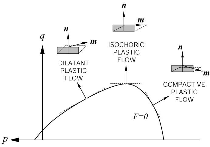
The so called Cap models (Figure 3), based on a yield surface in the mean (or normal) stress-deviatoric (or shear) stress space known as pq space, describe the onset of deformation bands with various kinematics corresponding to distinctly different loading paths. The plastic strain increments are characterized by the relative velocity jump of the two sides of bands, 'm,' and the unit normal of the band planes, 'n.' The scalar products of 'm' and 'n' are equal to 1, 0, and -1 and correspond to pure dilation, simple shear (isochoric shear), and pure compaction, respectively (Borja and Aydin, 2004). The yield surface or the failure envelope has dilatant side (positive; 0 < m*n <1) and compactive side (negative; -1 < m*n < 0) and the bands corresponding to these sides may be dilatant and compactive shear bands, respectively, or shear enhanced dilation bands and shear enhanced compaction bands depending on the relative magnitudes of the shear and volumetric components of the deformation (Aydin et al., 2006; and Fossen et al., 2007). Other models such as anti-crack, inclusion, and localized volume reduction are referred to under 'Mechanisms and Mechanics of Volumetric Deformation Bands' and 'Mechanisms and Mechanics of Pressure Solution Seams.'

Representation of deformation bands in pq diagram and yield surface (F=0), sometimes referred to as the cap model. The positive and negative sides of the failure envelop represent hybrid models with both shear and volumetric components. The incremental plastic strain components are illustrated for dilatant, simple shear (isochoric), and compactive bands, where 'n' is the band normal vector and 'm' is the velocity jump across them. The product of m and n unity corresponds to pure dialtion, zero simple shear and -1 pure compaction band. From Borja and Aydin (2004) and Aydin et al. (2006).Figure 3. Representation of deformation bands in pq diagram and yield surface (F=0), sometimes referred to as the cap model. The positive and negative sides of the failure envelop represent hybrid models with both shear and volumetric components. The incremental plastic strain components are illustrated for dilatant, simple shear (isochoric), and compactive bands, where 'n' is the band normal vector and 'm' is the velocity jump across them. The product of m and n unity corresponds to pure dialtion, zero simple shear and -1 pure compaction band. From Borja and Aydin (2004) and Aydin et al. (2006).
Types of Mechanisms and Mechanics of Deformation Bands:
Mechanisms and Mechanics of Volumetric BandsMechanisms and Mechanics of Shear Bands
Mechanisms and Mechanics of Deformation Band ZonesMechanisms and Mechanics of Deformation Band SetsMechanisms and Mechanics of Multiple Deformation Band SetsMechanisms and Mechanics of Deformation Band Domains
Reference:

Antonellini, M., Aydin, A., 1994. Effect of faulting on fluid flow in porous Sandstones: petrophysical properties. American Association of Petroleum Geologists Bulletin 78 (3): 355-377.

Aydin, A., Johnson, A.M., 1983. Analysis of faulting in porous Sandstones. Journal of Structural Geology 5 (1): 19 - 31.

Aydin, A., Borja, R., Eichhubl, P., 2006. Geological and mathematical framework for failure modes in granular rock. Journal of Structural Geology 28 (1): 83-98.

Aydin, A., Borja, R., Eichhubl, P., 2006. Geological and mathematical framework for failure modes in granular rock. Journal of Structural Geology 28 (1): 83-98.

Aydin, A., 2006. Failure modes of the lineaments on Jupiter's moon, Europa: Implications for the evolution of its icy crust. Journal of Structural Geology 28: 2222-2236, doi:10.1016/j.jsg.2006.08.003.

Borja, R., Aydin, A., 2004. Computational modeling of deformation bands in granular media, I: Geological and mathematical framework. Journal of Computational Mechanics and Engineering 193: 2667-2698.

Fossen, H., Schultz, R.A., Shipton, Z.K., Mair, K., 2007. Deformation bands in sandstone: a review. Journal of the Geological Society 164: 755-769.

Holcomb, D., Rudnicki, J.W., Issen, K.A., Sternlof, K.R., 2007. Compaction localization in the Earth and the laboratory: state of the research and research directions. Acta Geotechnica 2007 (2): 1–15.

Leach, P.W., 1985. Observation of adiabatic shear band formation in 7039 Aluminum alloy. Metallurgical Transections A 16A: 1900-1903.

Papka, S.D., Kyriakides, S., 1998. Experiments and Full-Scale Numerical Simulations of In-Plane Crushing of a Honeycomb. Acta Materialia 46(8): 2765-2776,​ ​http://dx.doi.org/10.1016/S1359-6454(97)00453-9.

Rudnicki, J.W., Rice, J.R., 1975. Conditions for the localization of deformation in pressure-sensitive dilatant materials. J. Mech. Phys. Solids 23: 371-394.


Readme    |    About Us    |    Acknowledgement    |    How to Cite    |    Terms of Use    |    Ⓒ Rock Fracture Knowledgebase