| |||||||
|
|
|||||||
|
|
|||||||
| Material Rotation | |||||||
|
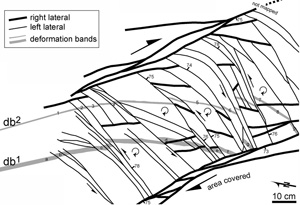
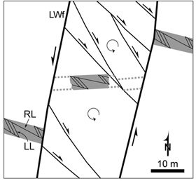
In a fault zone, rock fragments bounded by fractures can rotate as a result of fault interaction. Here, this is called material rotation associated with faulting. This concept is important in the successive splay fracturing model of weakness-based faulting. It makes it possible for shear stresses to be imposed on older fractures along the principal planes without any rotation of remote stresses. Flodin and Aydin (2004) show two field examples of material rotation observed in sandstone at Valley of Fire State Park, Nevada. In both examples, pre-existing deformation bands serve as markers of the rotation. Outside of the fault zone, both deformation bands continue with a straight trace for many meters. Within the fault zone, the deformation bands which act as passive markers are broken and offset by the faults. In the first example, shown in Figure 1, two sub-parallel, earlier-formed deformation bands (db1 and db2) enter the fault zone from the lower left and are progressively rotated in a clockwise sense with increasing distance to the lower right. In the second example, shown in Figure 2, a zone of pre-existing deformation bands is offset in a left-lateral sense by two segments of a strike-slip fault and in a right-lateral sense across the internal faults. The segments of the deformation band zone are rotated about 15 degrees in a counterclockwise sense. Also see Sylvester (1988) for examples of rotation associated with earthquake faults in California. | |||||||
| Reference: |
|||||||
| Flodin, E.A., Aydin, A., 2004 Sylvester, A.G., 1988 |
|||||||
|
Readme | About Us | Acknowledgement | How to Cite | Terms of Use | Ⓒ Rock Fracture Knowledgebase |
|||||||

