| |||||||||||||||
|
|
|||||||||||||||
|
|
|||||||||||||||
| Mixed Mode (Modes I/II and I/III) Joint Propagation | |||||||||||||||
|
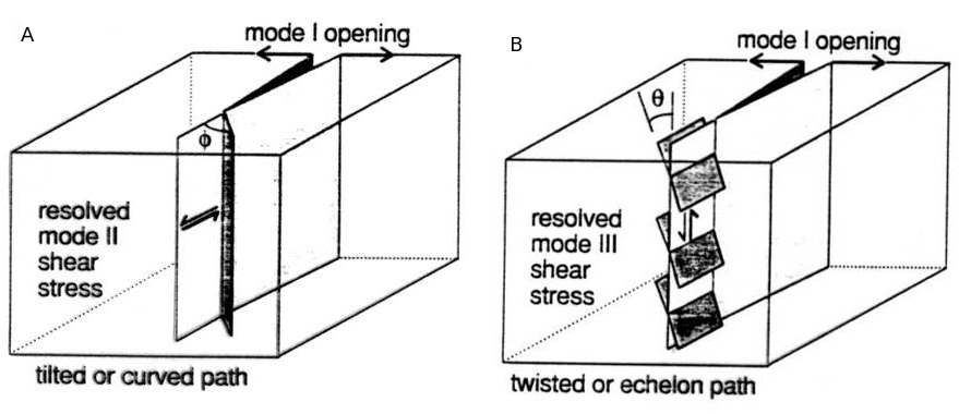
Mixed-mode joint propagation happens when the principal stress direction changes along the extension of the joint plane, and thus the shear component is resolved at the joint's front in addition to the crack normal component (mode I). When the shear component is perpendicular to the propagation front (mode II), the mixed mode is I-II (Figure 1A). When the shear component is parallel to the front (mode III), the mixed mode is I-III (Figure 1B). In both cases, the preferred joint path is out of plane and tends to be oriented perpendicular to the local maximum tension.
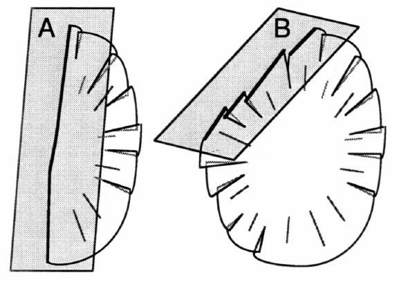
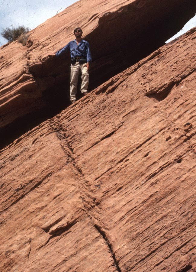
In mixed I-II mode (Figure 1A), a remote loading system or a local stress field resolves a shear component perpendicular to the propagation front. Then, the next joint growth increment will be of mixed mode (I and II) and the crack path will deviate from the in-plane extension of the crack. This results in a kink in the crack path. The sense of the deviation is similar to that of the shearing and the magnitude of the kink angle is largely controlled by the ratio of KI over KII as well as the cohesive end zone geometry. In mixed I-III mode (Figure 1B), the shear stress component at the propagation front is oriented parallel to the front and the joint path is twisted about the front resulting in a breakdown of the joint path. The sense of the twist is consistent with that of the shear component. The magnitude of the twist (the angle, theta) is controlled by the ratio of KIII over KI as well as the interaction among the joint segments. The twisted joint paths in 3D may produce echelon joint traces in cross section depending on the orientation of the exposure surfaces (Figure 2). Figure 3 is a photograph of a joint showing the breakdown in response to mode I-III while propagating upward. In general, joints propagating in three dimensions may include both of the mixed modes referenced above.
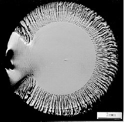
Changes in the orientation of a joint's surface can be sharp or smooth, depending on the stress gradient at the time. A temporal change in the loading conditions can produce sharp changes in joint path. A stress field varying smoothly in space can produce a gradually curving joint path. Joint surface morphology is a direct expression of the joint paths. Tilted paths produce rib structures and kinks. Twisted paths produce hackles or lances, and fringe joints (Figure 4). Using these common structures, it is possible to infer the mode of fracture and the stress state responsible for it.
| |||||||||||||||
| Reference: |
|||||||||||||||
| Pollard, D.D., Aydin, A., 1988 Sommer, E., 1969 |
|||||||||||||||
|
Readme | About Us | Acknowledgement | How to Cite | Terms of Use | Ⓒ Rock Fracture Knowledgebase |
|||||||||||||||