Rock Fracture
KNOWLEDGEBASE
  

Mechanisms and Mechanics of Echelon Joints

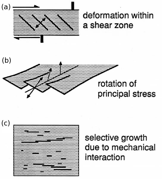
There are several models for the formation of echelon joints. Some of these are illustrated and the underlying mechanisms are listed in Figure 1. Each mechanism has been detailed under 'Riedel Shears,' 'Mixed-Mode Joint Propagation,' and 'Interaction of Joints.' Figure 1(a) shows a shear zone, the boundaries of which constrain the extent and distribution of the joints thereby producing a highly overlapped joint zone. Figure 1(b) shows an initially single joint breaking down to echelon joints as a result of mode I-III loading (Pollard et al., 1982; Pollard and Aydin, 1988). Figure 1(c) illustrates formation of echelon joint arrays due to interaction of neighboring joints which promotes selective growth of joints in certain alignments (Du and Aydin, 1991).

Possible formation mechanisms of echelon joints.Figure 1. Possible formation mechanisms of echelon joints.

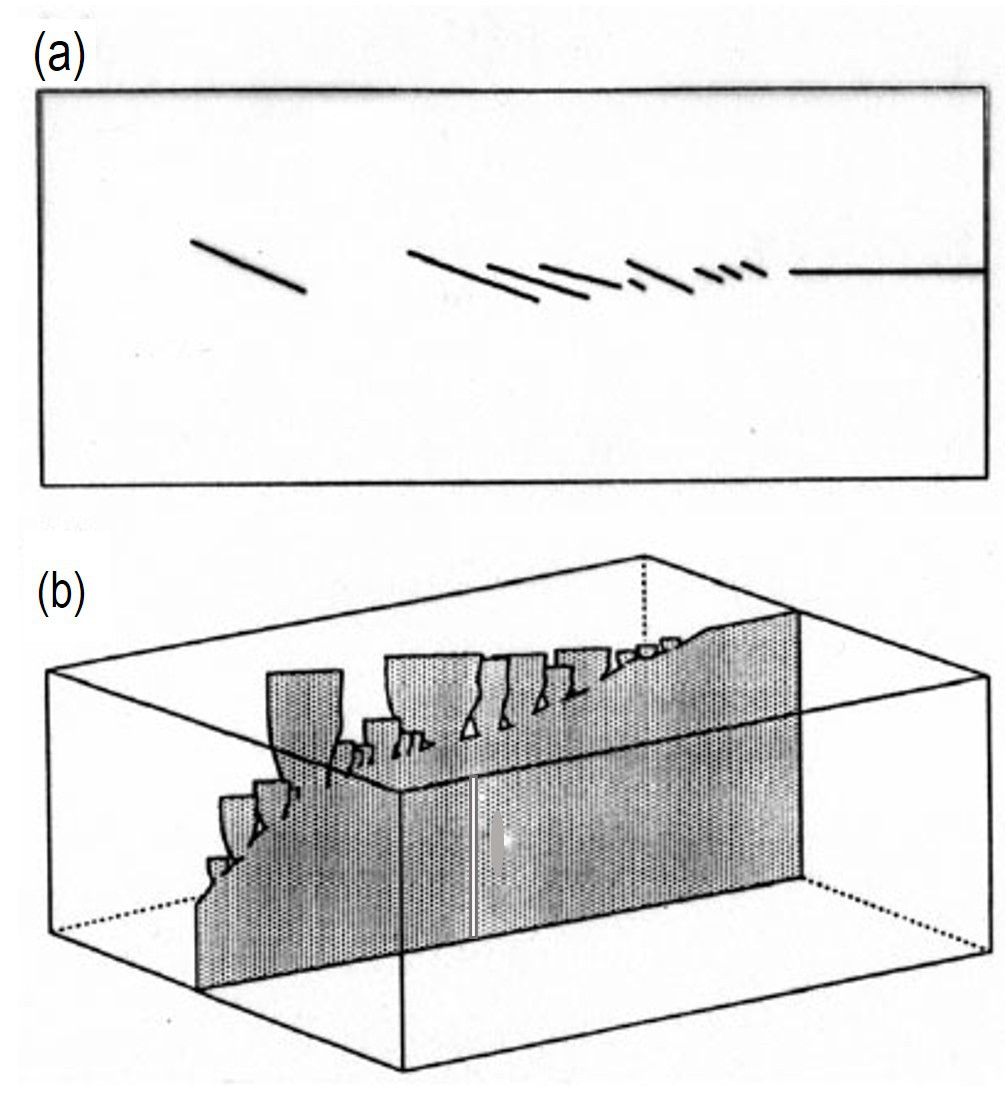
Figure 2(a) shows formation of echelon joint traces in front of a parent joint trace (Cruikshank et al., 1991). These may be considered as the 'Fringe Joints.' Figure 2(b) is a hypothetical block diagram by the same authors illustrating how such echelon joint arrays in 2(a) may be connected to the parent joint or sheared joint at depth.

(a) Trace geometry of echelon joints in front of a parent joint, and (b) how joints twist and connect to the parent joint at depth. From Cruikshank et al. (1991).Figure 2. (a) Trace geometry of echelon joints in front of a parent joint, and (b) how joints twist and connect to the parent joint at depth. From Cruikshank et al. (1991).

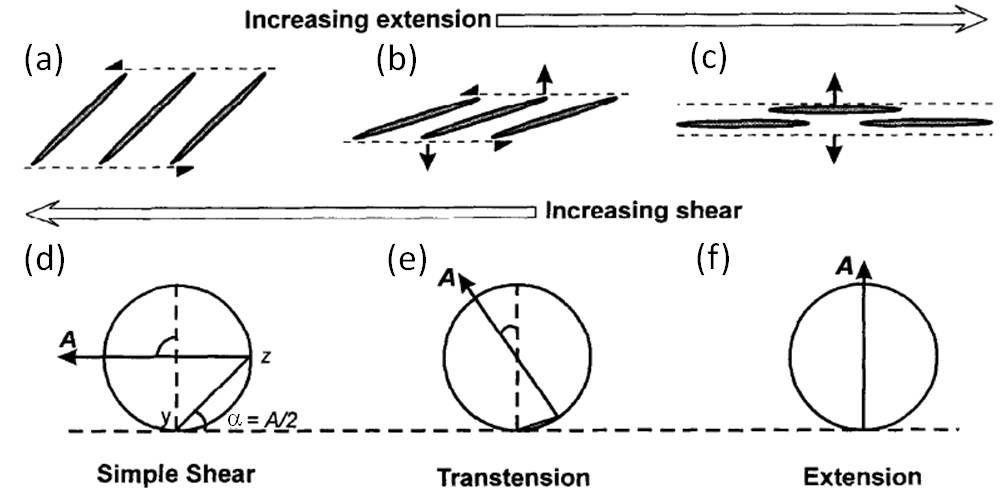
Figure 3 shows progressive rotation of echelon joints making progressively smaller angles to the sheared boundaries (Kelly et al., 1998).

Schematic diagrams illustrating relationships between echelon fracture orientation with increasing extension perpendicular to the fracture zone (a to c). Also shown are the direction (alpha) and the relative magnitudes of shearing and extension associated with various loading configurations, from simple shear (d) to shearing and tension (e) and pure extension (f). In essence, a spectrum of echelon joint geometry, some under various loading configurations. From Kelly et al. (1998).Figure 3. Schematic diagrams illustrating relationships between echelon fracture orientation with increasing extension perpendicular to the fracture zone (a to c). Also shown are the direction (alpha) and the relative magnitudes of shearing and extension associated with various loading configurations, from simple shear (d) to shearing and tension (e) and pure extension (f). In essence, a spectrum of echelon joint geometry, some under various loading configurations. From Kelly et al. (1998).
Reference:

Cruikshank, K.M., Zhao, G., Johnson, A.M., 1991. Analysis of minor fractures associated with joints and faulted joints. Journal of Structural Geology 13: 865-886.

Du, Y., Aydin, A., 1991. Interaction of multiple cracks and formation of echelon crack arrays. International Journal of Analytical and Numerical Methods in Geomechanics 15: 205-218.

Kelly, P.G., Sanderson, D.J., Peacock, D.C.P., 1998. Linkage and evolution of conjugate strike-slip fault zones in limestones of Somerset and Northumbria. Journal of Structural Geology 20: 1477-1493.

Pollard, D.D., Segall, P., Delaney, P.T., 1982. Formation and interpretation of dilatant echelon cracks. Geological Society of America Bulletin 93: 1291-1303.

Pollard, D.D., Aydin, A., 1988. Progress in understanding jointing over the past century. Geological Society of America Bulletin 100 (8): 1181-1204.


Readme    |    About Us    |    Acknowledgement    |    How to Cite    |    Terms of Use    |    Ⓒ Rock Fracture Knowledgebase