| ||||||||||||
|
|
||||||||||||
|
|
||||||||||||
| Three or More Sets of Joints | ||||||||||||
|
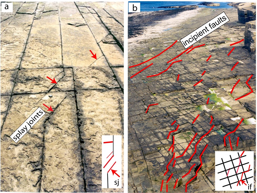
The polygonal joints under the class 'Multiple Joint sets' are good examples of contemporaneous multi sets of joint systems. There are also other three or more sets of fractures each of which formed as opening mode fracture but some were sheared during the formation of the most recent one. Figure 1 shows a relatively clear case in which two initial orthogonal joint sets divide the flagstone on a pavement in northern Scotland into a chocolate tablet-shaped pattern. Although the orthogonal pattern is most impressive, a diagonal set in about the 2-o'clock direction can also be seen in Figure 1a (pointed by red arrows). The detailed photo in Figure 1b provides the critical information about the joints (red lines) defining the third set which are connected to the tips of the members of one of the orthogonal sets as splays indicating that the initial orthogonal joint sets were sheared. There is visual evidence that the third set members are related to the shearing of both orthogonal sets in the broader area.
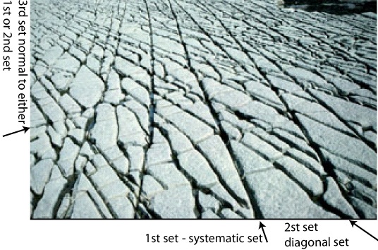
The second field example (Figure 2) comes from another wave-cut platform, this time in limestone at the Bristol Channel (UK). Here, the initial two sets are the systematic set and its splays and the third and the youngest set form normal to either the first or the second set. The one orthogonal to the second set is more common due to the narrow spacing of that set.
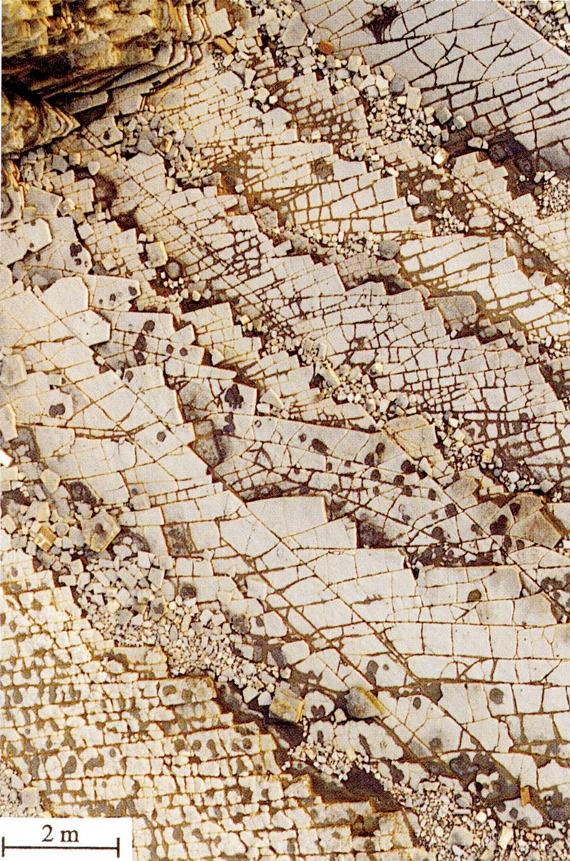
More complicated multiple sets of joints with more than three or four sets also exist (see the examples under 'Multiple Joint Sets', a higher hierarchy in our classification). Thermal or desiccation joints generally occur in more than two sets and are considered separately under 'Columnar Joints'. If multiple sets with more than two vertical sets do exist in tectonic environments, they indicate sequential shearing of the older sets. This pattern and its formation mechanics will be considered in 'Faulting by Shearing of Joints.' The photograph in Figure 3 shows a much more complex scenario in which joint patterns show a significant variation from one bed to another in successive beds. When sequences of beds are not identified due to large distance between the jointed exposures or cover of the transition from one bed to another, this variation in joint orientations may appear to form in the same continuous medium and thus lead to mechanical misinterpretation.
| ||||||||||||
| Reference: |
||||||||||||
| Auzias, V., Rives, T., Rawnsley, K.D., Petit, J.P., 1997 |
||||||||||||
|
Readme | About Us | Acknowledgement | How to Cite | Terms of Use | Ⓒ Rock Fracture Knowledgebase |
||||||||||||