| |||||||
|
|
|||||||
|
|
|||||||
| Joint Propagation Direction | |||||||
|
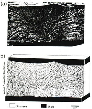
As noted earlier under 'Initiation of Joints,' joints usually start from a point or a planar defect or flaw. They then propagate in a plane in 3-D space. While the initiation is largely controlled by the size, orientation, shape, and distribution of flaws, the propagation of joints are controlled by loading as well as configuration of the medium. Joint propagation history can be read from joint surface features (Figure 1a), such as hackles, ribs, or hesitation marks. Hackles form parallel to the local propagation direction and perpendicular to the joint front. Hence, it is possible to construct successive joint fronts graphically by simply drawing curves perpendicular to heckle marks (Figure 1b). By this method, the growth kinematics of a joint can be deciphered using the principles of fractography. For example, it is safe to conclude that the joint in Figure 1 started from a cusp at the base of the layer, to which the hackles converge. It then propagated in all 180 degrees until the front reached the top of the layer. After this point the overall propagation is primarily lateral along the layer. Please find more information on joint propagation under 'Surface Morphology / Roughness of Joints - Plumose Structure.' Keep in mind that it is not possible to determine absolute joint propagation velocity from the method described above. | |||||||
| Reference: |
|||||||
| Helgeson, D., Aydin, A., 1991 |
|||||||
|
Readme | About Us | Acknowledgement | How to Cite | Terms of Use | Ⓒ Rock Fracture Knowledgebase |
|||||||
