Rock Fracture
KNOWLEDGEBASE
  

Surface Morphology / Roughness of Joints - Plumose Structure

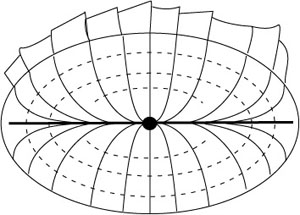
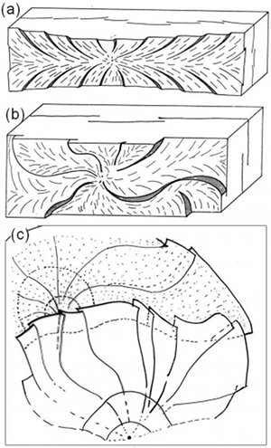
Plumose structure (Figures 1 and 2) is common on joint surfaces. It consists of hackle marks that fan away from an axis, curvilinear markers called rib marks, and an initiation point (origin). Away from the origin, there are often mirror, mist, and hackle zones. Sometimes hackle marks grow larger and rotate visibly at the border of joints. Because of their location with respect to the rest of the joint plane, they are called fringe joints. Plumose structures can be used to determine the initiation points even when the actual initiation points are not visible. Hackle marks converge to the initiation points. Stress distribution in a layer may give rise to either symmetric (Figure 2a) or asymmetric (Figures 2b and c) plumose patterns.

Idealized drawing showing joint surface morphology. The ellipse outlines a plumose structure, with the dot at the center as the initiation point, heavy horizontal line as the plumose axis, and the lines fan out from the initiation point and the axis as hackle marks. Dash lines represent rib marks. Fringe joints are drawn at the top boundary of the plumose structure.Figure 1. Idealized drawing showing joint surface morphology. The ellipse outlines a plumose structure, with the dot at the center as the initiation point, heavy horizontal line as the plumose axis, and the lines fan out from the initiation point and the axis as hackle marks. Dash lines represent rib marks. Fringe joints are drawn at the top boundary of the plumose structure.
Plumose patterns in layered rocks. (a) and (b) common patterns in thin layers, the former being symmetric with linear plum axis and the latter being asymmetric with highly curved plum axes. (c) Plumose in thick layers or in massive rock bodies with either amalgamated layers or no layering.Figure 2. Plumose patterns in layered rocks. (a) and (b) common patterns in thin layers, the former being symmetric with linear plum axis and the latter being asymmetric with highly curved plum axes. (c) Plumose in thick layers or in massive rock bodies with either amalgamated layers or no layering.

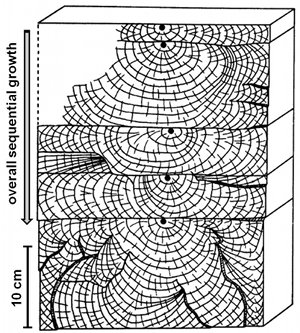
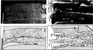
In layered rocks, a joint, once initiated, propagates mostly laterally because layer thickness is smaller than other dimensions of layers. The vertical growth of joints generally occurs by propagation of joints from one layer (either depositional or mechanical) to the next (Figure 3 and Figure 4). The implication of these patterns for incremental joint growth is that the initiation points are located at the leading front of the trailing segments and the terminations are marked by fringe joints.

Map showing sequential evolution of jointing in layered sedimentary rock, near Watkins Glenn, NY. From Helgeson and Aydin (1991).Figure 3. Map showing sequential evolution of jointing in layered sedimentary rock, near Watkins Glenn, NY. From Helgeson and Aydin (1991).
Kinematics of joint propagation. Top row shows outcrop photos and bottom row shows schematic drawings. In the drawings, short lines show hackle marks and continuous thin lines, drawn normal to the hackle marks, show past positions of propagation fronts at arbitrary times. The column on the left shows almost co-planar joints, with each numbered joint mostly in the plane of the previous one. Their origins lie to the right of the area photographed. The column on the right shows non-coplanar joints. The numbered joints diverge from the plane of the previous one. From DeGraff and Aydin (1987).Figure 4. Kinematics of joint propagation. Top row shows outcrop photos and bottom row shows schematic drawings. In the drawings, short lines show hackle marks and continuous thin lines, drawn normal to the hackle marks, show past positions of propagation fronts at arbitrary times. The column on the left shows almost co-planar joints, with each numbered joint mostly in the plane of the previous one. Their origins lie to the right of the area photographed. The column on the right shows non-coplanar joints. The numbered joints diverge from the plane of the previous one. From DeGraff and Aydin (1987).

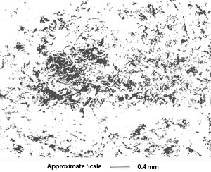
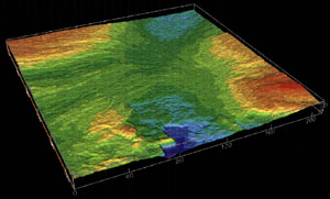
The roughness of joint surface can be visualized by various techniques. Figure 5 shows an example using Wood's metal injection test using two symmetric natural fracture surfaces of a granitic sample subjected to a normal stress of 33 MPA. Figure 6 shows a laser profilometer image of a joint surface topography in siltstone. The figures illustrate the inherent variation of the spatial distribution of natural fracture topography and divergence from ideal planar geometry. Images of the opposing joint surfaces can be used to calculate joint aperture and visualize formation of open channels when the opposing joint surfaces move relative to each other.

Composite SEM micrograph of Wood's metal casts of two natural fractures showing void space at 33 MPa effective stress. Void space, filled by Wood's metal, is shown in white; contact areas are black. From Pyrak-Nolte et al. (1992).Figure 5. Composite SEM micrograph of Wood's metal casts of two natural fractures showing void space at 33 MPa effective stress. Void space, filled by Wood's metal, is shown in white; contact areas are black. From Pyrak-Nolte et al. (1992).
Laser profilometer image of a joint surface in siltstone sample of about 20x20 cm showing the variation of surface topography from an arbitrary plane (click on the picture to see the plane). Laser survey thanks to William Durham formerly of Lawrence Livermore National Laboratory.Figure 6. Laser profilometer image of a joint surface in siltstone sample of about 20x20 cm showing the variation of surface topography from an arbitrary plane (click on the picture to see the plane). Laser survey thanks to William Durham formerly of Lawrence Livermore National Laboratory.

The development of the concept of fractal geometry in the 1970s has revealed that the shape and pattern of all types of natural fractures carry valuable information. Brown and Scholz (1985) analyzed the roughness of natural rock fracture surfaces over a broad band of spatial frequencies and found fractal dimension varied with frequency. From this study, they concluded that rock surface roughness was not self-similar on all scales and no simple scaling laws exist. Brown (1987) suggested that the scaling properties of rock fractures depended not only on their fractal dimensions but also on the minimum horizontal resolution at which the profile must be measured in order to produce a valid estimation of fractal dimension.

Types of Surface Morphology / Roughness of Joints - Plumose Structure:
OriginHackle MarksRib MarksMirror and Mist
Reference:

Aydin, A., Borja, R., Eichhubl, P., 2006. Geological and mathematical framework for failure modes in granular rock. Journal of Structural Geology 28 (1): 83-98.

Brown, S.R., Scholz, C.H., 1985. Broad bandwidth study of the topography of natural rock surfaces. Journal of Geophysical Research - Solid Earth and Planets 90 (B14): 12575-12582.

Brown, S.R., 1987. A note on the description of surface roughness using fractal dimension. Geophysical Research Letters 14: 1095-1098.

DeGraff, J.M., Aydin, A., 1987. Surface morphology of columnar joints and its significance to mechanics and direction of joint growth. Geological Society of America 99 (5): 605-617.

Helgeson, D., Aydin, A., 1991. Characteristics of joint propagation across layer interfaces in sedimentary rocks. Journal of Structural Geology 13 (8): 897-911.

Pollard, D.D., Aydin, A., 1988. Progress in understanding jointing over the past century. Geological Society of America Bulletin 100 (8): 1181-1204.

Pyrak-Nolte, L.J., Myer, L.R., Nolte, D.D., 1992. Fractures: Finite-size scaling and multifractals. Pure and Applied Geophysics 138(4): 679-706.


Readme    |    About Us    |    Acknowledgement    |    How to Cite    |    Terms of Use    |    Ⓒ Rock Fracture Knowledgebase