| |||||||
|
|
|||||||
|
|
|||||||
| Anticrack Model | |||||||
|
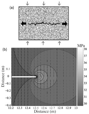
Fletcher and Pollard (1981) proposed that once initiated from a flaw, pressure solution seams propagate through rock in its own plane as 'anticracks' or closing-mode structures. At the macroscopic level, a pressure solution structure propagates in a manner similar to that of a joint loaded in tension, except that pressure solution forms in compression (Figure 1a). The displacement discontinuity is oriented parallel to the maximum compressive stress and perpendicular to the dissolution zone, and then the stress concentration at the tip region obtained by numerical Boundary Element Method drives the structure to grow (Figure 1b). Since the regions of high compressive stress experience enhanced pressure solution, further propagation of planar dissolution in the direction perpendicular to the maximum compressive stress can be predicted. Fletcher and Pollard (1981) and later Sternlof et al. (2005), modeling a similar type of structure (compaction bands), concluded the following: (1) Solution seams are bounded longitudinally. This implies that the displacement discontinuity which probably starts from a flaw, must die off toward the terminations. (2) The residue thickness and amplitude varies from a maximum near the center to zero at the tips, please refer to the sections 'Morphology of Stylolites' and 'Residue Thickness Distribution' for detail. This implies that at the center the process occurs more intensely or for a longer duration, and consequently more material is dissolved and removed. (3) The maximum dissolved thickness is proportional to the length of the structure, in this case pressure solution seam. | |||||||
| Reference: |
|||||||
| Aydin, A., Borja, R., Eichhubl, P., 2006 Fletcher, R.C., Pollard, D.D., 1981 Sternlof, K.R., Rudnicki, J.W., Pollard, D.D., 2005 |
|||||||
|
Readme | About Us | Acknowledgement | How to Cite | Terms of Use | Ⓒ Rock Fracture Knowledgebase |
|||||||
