| |||||||
|
|
|||||||
|
|
|||||||
| Composite Faults | |||||||
|
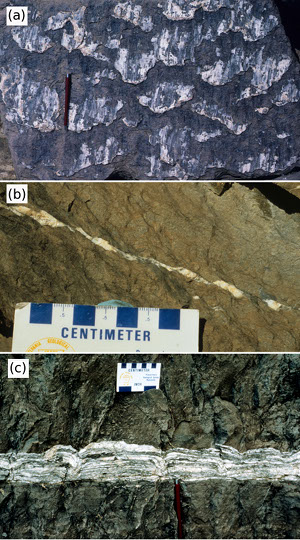
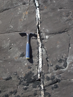
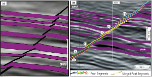
Recalling the concept of composite joints, it is easy to relate to composite small faults illustrated in a series of photographs and maps in Figure 1 from the Bays Mountain anticline, northwestern Tennessee (please see the Bays Mountain case study link). Figure 1(a) shows a series of calcite filled fault surfaces delineating the individual fault segments altogether defining a composite fault. Figure 1(b) is a cross sectional view of a similar structure showing multiple echelon segments sub-parallel bedding, which control the dilation and localized calcite precipitation at the stopovers. Figure 2 illustrates a composite right-lateral strike-slip fault with 40 cm slip as seen on a sandstone pavement. Figure 3 is a larger scale example of a similar case in alternating units of fractured siltstone and deformed shale units based on the seismic interpretations of a series of normal fault segments in the subsurface. Figure 3(a) is an incipient normal fault zone illustrating faulted sand units. Obviously, here the ductility of the shale units plays a crucial role as discussed under faulting of alternating brittle and ductile multilayers. However, the faults in sands on both sides of each shale unit are mechanically communicating which is why the product is a composite fault rather than a series of independent small faults in different units. Figure 3(b) represents a more mature fault zone with highly overlapped fault segments (numbered for reference in the figure - also see 'Faulting by Shale Smearing'). | |||||||
| Reference: |
|||||||
| Koledoye, B., Aydin, A., May, E., 2003 Nenna, F., Aydin, A., 2011 Ohlmacher, G., Aydin, A., 1995 |
|||||||
|
Readme | About Us | Acknowledgement | How to Cite | Terms of Use | Ⓒ Rock Fracture Knowledgebase |
|||||||


