Rock Fracture
KNOWLEDGEBASE
  

Conjugate Faults

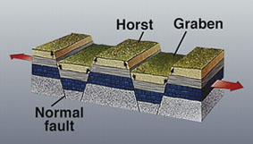
The term conjugate faults refers to a configuration of two sets of faults with opposite sense of shearing. They generate horsts (uplifted blocks) and grabens (depressed blocks) as illustrated schematically in a diagram in Figure 1.

A series of normal faults dipping in opposite directions and bounding horsts (uplifted blocks) and grabens (depressed blocks). From USGS, available from http://commons.wikimedia.org/wiki/Image:Horst_graben.jpg.Figure 1. A series of normal faults dipping in opposite directions and bounding horsts (uplifted blocks) and grabens (depressed blocks). From USGS, available from http://commons.wikimedia.org/wiki/Image:Horst_graben.jpg.

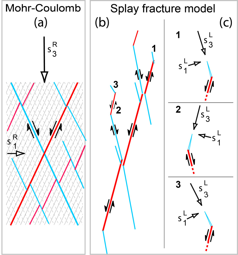
There are two types of conjugate fault patterns depending on their formation mechanisms. The first one is also known as the Anderson's model in which conjugate faults form as shear fractures under a single static remote stress field as illustrated in Figure 2(a). The angle between the two sets depends on the friction coefficient across the faults, which is commonly 0.6 corresponding to a friction angle of 30 degrees. In this case, the largest compressive or the least tensile principle stress bisects the acute intersection angle between two sets and the intermediate principal stress lies along the intersection line of the two sets.

(a) Conjugate faults formed as shear fracture in pristine rocks according to Mohr-Coulomb failure. In this case, the acute angle between the two features with opposite sense of shearing is bisected by the remote greatest compressive stress. Figures 2(b) and 2(c) illustrate formation of conjugate faults by another another mechanism, here referred to as splay fracturing and successive shearing of splay fractures labelled as 1, 2, 3 in (b). Local stress orientations are marked in (c). From Davatzes (2003).Figure 2. (a) Conjugate faults formed as shear fracture in pristine rocks according to Mohr-Coulomb failure. In this case, the acute angle between the two features with opposite sense of shearing is bisected by the remote greatest compressive stress. Figures 2(b) and 2(c) illustrate formation of conjugate faults by another another mechanism, here referred to as splay fracturing and successive shearing of splay fractures labelled as 1, 2, 3 in (b). Local stress orientations are marked in (c). From Davatzes (2003).

An alternative mechanism of formation of conjugate faults is shearing of an initial discontinuity, splay fracturing, and sequential shearing of the splays (Figures 2(b) and (c)). To distinguish this from the former, this is referred to as apparent conjugate configuration which is different than the former in terms of the mechanisms and the resulting geometry (Davatzes, 2003).

Reference:

Davatzes, N.C., 2003. Fault architecture as a function of deformation mechanism in clastic rocks with an emphasis on sandstone. PhD Dissertation, Stanford University.


Readme    |    About Us    |    Acknowledgement    |    How to Cite    |    Terms of Use    |    Ⓒ Rock Fracture Knowledgebase