| |||||||
|
|
|||||||
|
|
|||||||
| Fractures in Monterey Formation, CA, USA | |||||||
|
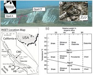
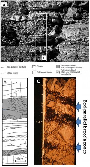
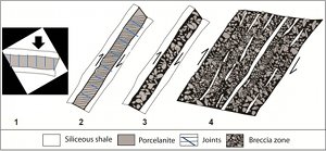
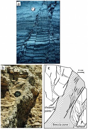
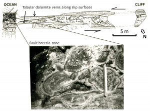
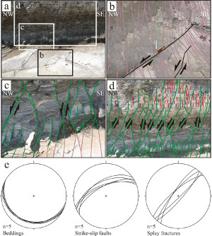
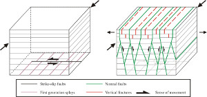
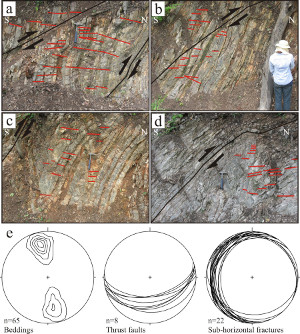
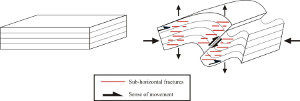
A thermomechanical silica diagenesis and phase transformation have interesting consequences for faulting of the Monterey Formation in the Neogene Basins along the San Andreas Fault in California (see Inset in Figure 1 for location). A type locality to decipher this kind of faulting, which falls into a category that we referred to as sheared-joint based faulting, is the Chico Martinez Creek (CMC) outcrop in central California (see the annotated photograph in Figures 1a and 1b). There, the Antelope Shale of the Monterey Formation is well-exposed on the eastern bank of the CMC as shown in the panoramic picture, and includes a relatively sharp boundary between opal A to opal CT marking the diagenetic conversion from a relatively pure biogenic silica, also referred to as diatomite, to porcelanite affected by relative weight percentage of biogenic silica and temperature (Figure 1c). See Isaacs (1982) and Behl and Garrison (1994) for details. Although opal A section in Figure 1 has some fractures in spite of its high porosity, opal Ct or porcelanite is much more stiffer and therefore extremely fracturable. In addition, alternating thin beds of siliceous shale and porcelanite leads to bed-parallel shearing and localized splay jointing (Figure 1b). See, Dholakia et al (1999) for details. It has also been suggested that the shale units are prone to faulting by shear fracturing while the porcelanite beds, or quartz, which is the higher order term of the transformation series, deform by jointing. This dual behavoir was coined as strain partioning by Gross (1995). The fracturing and faulting process produce a highly fragmented rock as the joint density increases and shearing of the earlier joints break the rock into breccia. Figure 2 shows such a system of bed-parallel faults with the associated breccia zones filled by tar in the Chico Martinez Creek outcrop (2a and 2b) and in a core extracted from the Cymric field, central California (2c). Figure 3 illustrates a conceptual model for progressive evolution of fracturing and fragmentation and brecciation from pre-tilting, bed-perpendicular jointing (1), through shearing of earlier joints and the formation of a new joint set by splaying mechanism (2). Finally, breccia zones form along thinly bedded porcelanite between bed-parallel shear zones (3 and 4). These high porosity zones are commonly filled by either cement, groundwater or tar. Just to complete the discussion of the faulting of the Monterey Formation, we refer to fault related cementations and brecciation which are associated with shearing of the joints at high-angle to bedding. This mechanism can also produce faults with significant breccia zones but this time at high-angle to bedding (Figure 4a, b, c). This mechanism is the same as other sheared joint-based faulting described in detail somewhere else in this Knowledgebase. Finally, diagenetic cementation associated with shearing of joints at high-angle to bedding has important consequences for both during the faulting and afterwards. Figure 5 is an example for such an architecture of a fault zone with about 4 m left-lateral slip, in which tabular bodies of dolomite cement occur adjacent to, and parallel with, the slip surfaces. A thick breccia zone is present between the bounding slip surfaces (Figure 5 inset). For more details of this process as well as additional examples, see Eichhubl and Boles (2000). Recent studies at the Arroyo Burro beach, Santa Barbara by Kanjanapayont et al. (2016) provided more details of various fault types and the related fractures complementing Gross et al. (1998). Nearly 3-D outcrops along the wave-cut platform on either sides of the Mesa Lane staircase to the beach provide excellent views of the structural details. Figures 6 (a to d) are photographs with maps documenting strike-slip faults and their splays (Figure 6(e)), the shearing of which produced a series of normal faults and related high-angle joints. The schematic diagrams in Figure 7 illustrate these sequences. Figures 8 (a to d) show examples of fairly steep reverse/thrust faults in various orientation with respect to bedding (see Figure 8e for orientations). These thrust faults are commonly surrounded by sub horizontal joints, the orientation of which is also shown in Figure 8 (e). The diagrams in Figure 9 depict folding and thrusting both low-angle and high-angle cinfigurations and the related sub horizontal joints. From a broader perspective, the Neogene Basins along the transform boundary across California contain detrital sediments of a wide variety of properties related to depositional and diagenetic in origin. These rocks have been subjected to shearing as well as contraction/extension, which are presently on-going. The features including different fault types referred to above may have occurred in different spatial and temporal domains or they may have formed within the same domain. See the link, Assemblages of Different Types of Faults, for examples of coexistence of types of faults with various kinematics. | |||||||
| Reference: |
|||||||
| Barnett, J., 1987 Behl, W.C., Garrison, 1994 Dholakia, S.K., Aydin, A., Pollard, D.D., Zoback, M.D., 1998 Eichhubl, P., Boles, J.R., 1998 Eichhubl, P., Boles, J.R., 2000 Gross, M.R., Gutierrez-Alonso, G., Bartlett, W.L., 1998 Isaacs, C.M., 1982 Kanjanapayont, P., Aydin, A., Wongseekaew, K., Moneelok, W., 2016 |
|||||||
|
Readme | About Us | Acknowledgement | How to Cite | Terms of Use | Ⓒ Rock Fracture Knowledgebase |
|||||||
