| |||||||||||||||||||||||||||||||||
|
|
|||||||||||||||||||||||||||||||||
|
|
|||||||||||||||||||||||||||||||||
| Growth of Faults based on Sequential Shearing of Initial Discontinuities | |||||||||||||||||||||||||||||||||
|
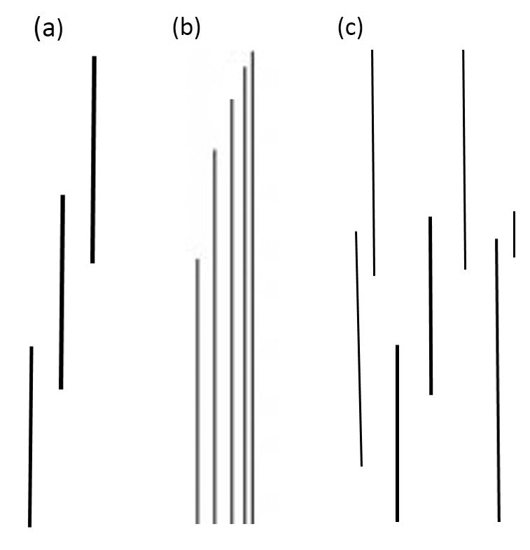
This process was described in two case studies, 'Fractures in Sierra Nevada, CA, USA' and 'Fractures in Monterey Formation, CA, USA.' We focus here on the growth of faults in sandstone because we documented this process in various publications. However, the concepts are applicable to other lithologies in other locations. Figure 1 includes a few of the most common patterns of joints which generally form earlier than shear fractures due to the fact that rocks generally have low tensile strength as mentioned before. Figure 1(a) shows an isolated echelon co-linear joint array, and Figures 1(b) and (c) show sub-parallel multi-elements with a variety of geometric patterns and tip distributions, which play a unique role in the initiation and growth process of the faults formed by their shearing. This process is often referred to as sequential shearing and linkage.
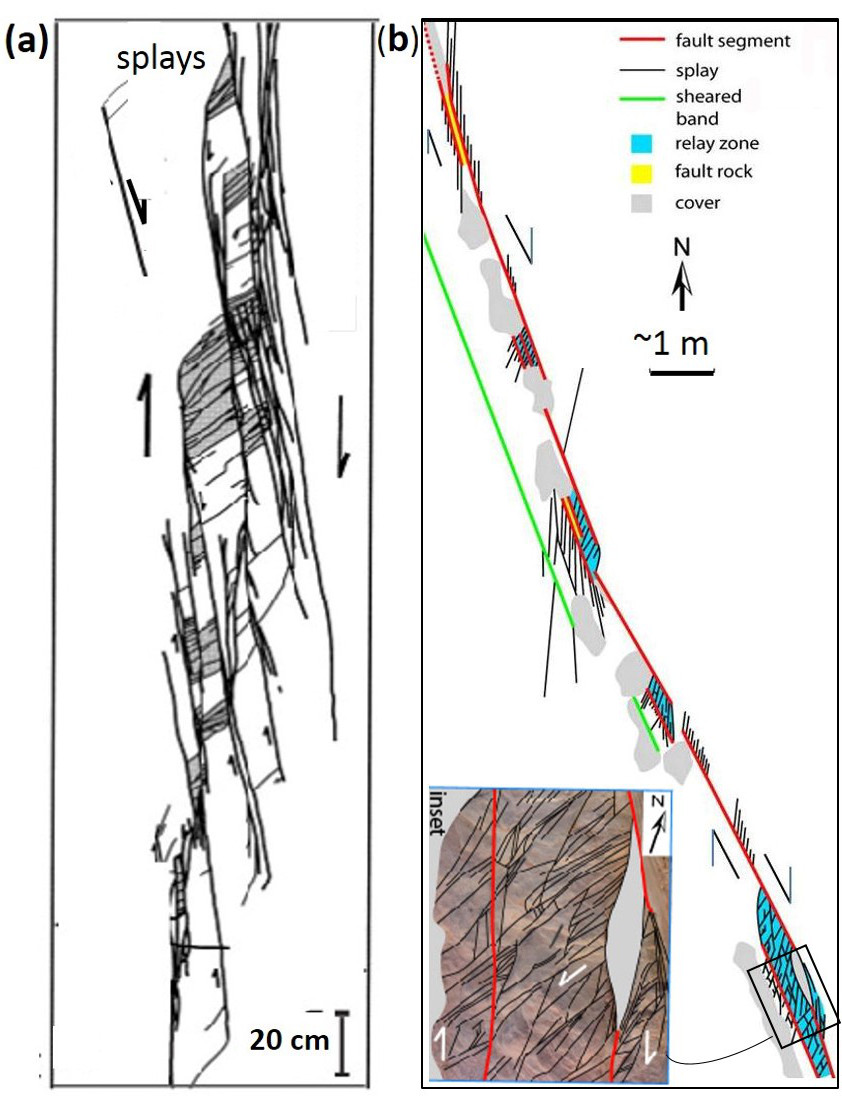
Figure 2(a) shows a series of sheared joints in an echelon pattern exposed on a pavement of the Jurassic aeolian Aztec Sandstone in Valley of Fire State Park, southeastern Nevada. The map and its interpretation indicate about 1 or 2 cm right-lateral slip across each segment and many high-angle splay fractures which are clustered at or near their ends, specifically at their stepovers or relays. The splays with high density in some stepovers divide the rock blocks between the neighboring small faults into thin tabular slabs, which themselves are not stable (Peng and Johnson, 1972). However, the rock bodies are still intact. Figure 2(b) illustrates a case with about 80 cm slip also in a right-lateral sense. The detail map of the fractures at one of the stepovers indicates that at least three sets of fractures are present and that they formed by sequential shearing and splaying. Note that only one of the sets, the youngest one, can still be in opening mode because they are not orthogonal to each other and the older sets are sheared joints with minute amount of slip.
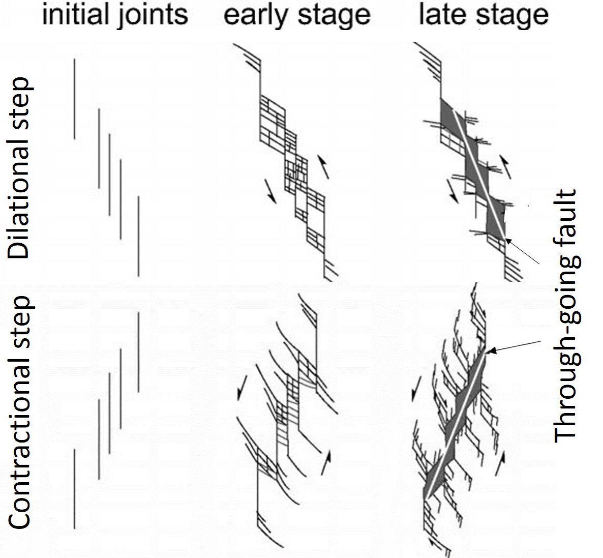
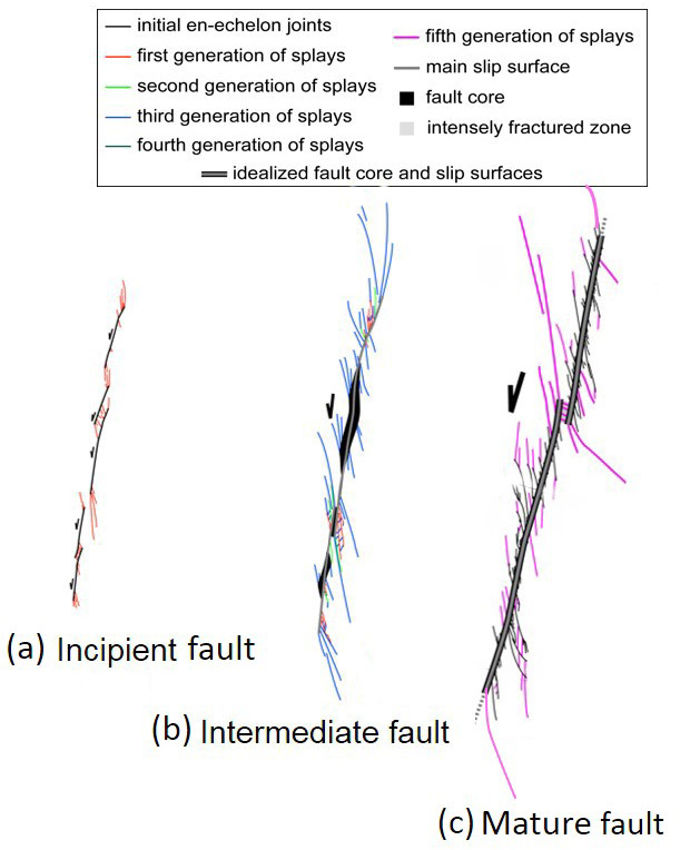
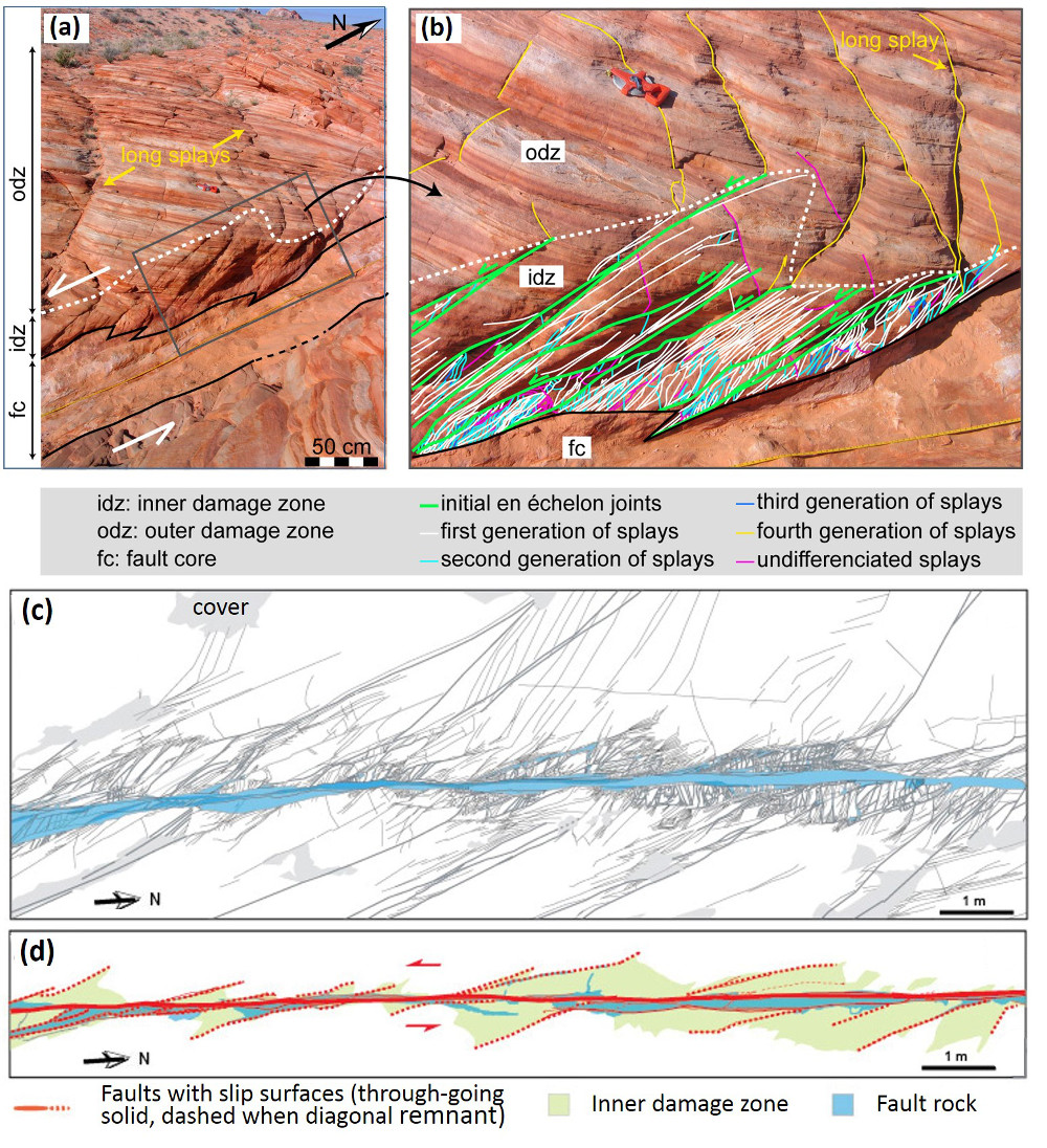
It is important to keep in mind that the intersecting joints and sheared joints are critical for further weakening the fractured rock. The diagrams in Figure 3 illustrate types and progressive evolution of linkage of segments through fracturing. The tensile or extension quadrants with dense fracture patterns are located either inside of the array (Figure 3a) or outside of it (Figure 3b). Even though, the slabs at the compressive stepovers can also be fractured and eventually deform inelastically by cataclasis, the splays within the extensional regions are more prone to further fracturing leading to the formation of fault rock and the surrounding damage zone. These concepts are illustrated schematically in Figures 4a, b, and c in a hierarchical manner (de Joussineau and Aydin, 2007). The areas with inner damage zones having a high density of intersecting fractures eventually become too weak to maintain their integrity and are assimilated by the fault core. This progressive deformation facilitates the linkage of prior segments to increase the fault length and sideways widening of the damage zone and ensuing cataclasis to increase its thickness (Myers and Aydin, 2004; and de Joussineau and Aydin, 2007).
Figures 5(a) and (b) are photographs and maps of a portion of a fault with 14 m left-lateral slip as seen on a pavement of Aztec Sandstone at Valley of Fire State Park. Figures 5(c) and (d) show the architecture of a larger portion of this fault which inherited earlier fractures and faults, most of which were sheared off and were disconnected by the new through-going faults. These remnant elements can be readily identified based on their structurally misplaced positions with respect to the anatomy of the recently active through-going fault zone and their segments.
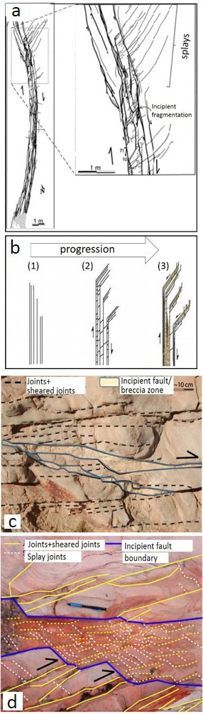
Figures 6(a) and (b) show a field map and conceptual diagram of a system of sub-parallel sheared joints whose tips are distributed systematically on the upper end (Myers and Aydin, 2004). The first and second order splays are localized at the extensional side. The closely spaced sub-parallel sheared joints define slender slabs which are also fractured. Figures 6(c) and (d) show a set of sheared joints with a new incipient fault zone defined by many steps and clusters of splays, the alignment of which in a direction favorable for shearing is probably the reason for the initiation of this fragmentation zone or breccia across the sub-parallel array. Interested readers may also examine shearing of a single joint set and two orthogonal joint sets.
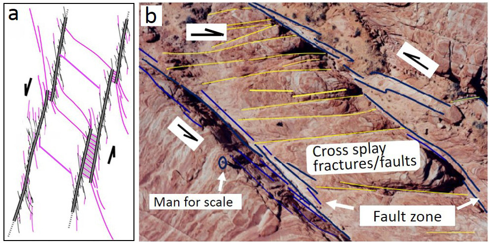
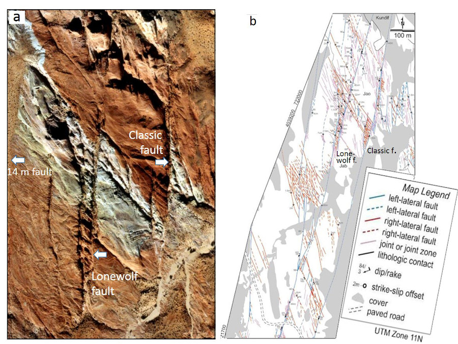
An effective process for increasing the width of a relatively large fault is fracturing and faulting of a wide zone of rock sliver between neighboring already developed mature faults or fault strands. Figures 7(a) and (b) show an example of this scale of fault growth from the Lonewolf fault with about 80 m predominantly left-lateral slip at Valley of Fire State Park. Figures 8(a) and (b) show a larger aerial photograph and a detailed structural map by Flodin and Aydin (2004) for location and structural setting. There, two mature fault strands of the Lonewolf fault with well developed fault rocks are connected by joint clusters and faults with opposite sense of shearing with respect to the bounding fault strands through a sliver of rock, about 25 m wide. It is rather straightforward to project that the Lonewolf fault would coalesce with the Classic fault with about 170 m left-lateral slip and about 100 m to the east to form a wider fault zone through the same mechanism if the slip across them would increase about an order of magnitude.
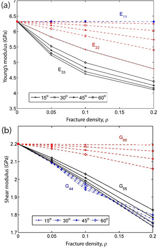
It has long been known that fractures mechanically weaken the rock volume in which they occur. This weakening can be quantified using the so-called effective medium theory by specifying primarily the fracture orientations and densities. The plots in Figures 9(a) and (b) are the three principal components of the Young's moduli and the shear moduli, respectively, as a function of two fracture arrays characterized by their densities and intersection angles. The analysis indicates that a significant reduction (~20-34%) in some components of the Young's and shear moduli with respect to the undisturbed medium should occur for modest fracture densities and common intersection angles between fault related fractures (Aydin and Berryman, 2010). It is also possible to interpolate the fracture densities and intersection angles corresponding to the vanishing values of these parameters, but the system would likely fail before the interpolated value.
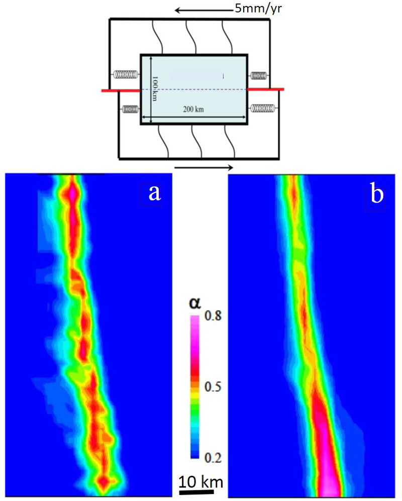
There has been an increasing number of efforts to simulate inelastic fault behaviors. For example, Lyakhovsky and Ben-Zion (2009) used a 3-D numerical model with a layered medium with viscoelastic rheology at depth to simulate damage in time and space around a crustal scale strike-slip fault (Figure 10(a)). These authors concluded that an independent scalar damage variable defined in terms of the strain invariants is sufficient to describe the crack density and its evolution (Figures 10(b) and (c)). There are two interesting aspects of the Lyakhovsky and Ben-Zion model: First, the damage parameter occurs in early stage in an echelon pattern beyond the initial planar discontinuity (Figure 10(b)). Second, the model results suggest that the early configurations are not stable and eventually lead to a smoother zone of localized damage distribution pattern in mature stages (Figure 10(c)). Inelastic deformation associated with high velocity dynamic fault propagation phenomena has also attracted considerable attention in the last decade . We have referred to a few of these studies in connection to fault branching. Please see the links 'Propagation of Faults' and 'Splay Faults/Splay Joints.' It turns out that both longitudinal and lateral fault growth are influenced by the fault propagation velocity (Dunham 2011a, and b). Fault interaction and linkage are also influenced by dynamic conditions since they cause variable stress perturbations ahead of a propagating rupture resulting in distribution of off-fault plastic strain different than that of the elastic strain distribution around faults in classical static solutions.
| |||||||||||||||||||||||||||||||||
| Reference: |
|||||||||||||||||||||||||||||||||
| Aydin, A., Berryman, J. G., 2010 Davatzes, N.C., Aydin, A., 2004 de Joussineau, G., Aydin, A., 2007 Dunham, E.M., Belanger, D., Cong, L., Kozdon, J.E., 2011a Dunham, E.M., Belanger, D., Cong, L., Kozdon, J.E., 2011b Flodin, E.A., Aydin, A., 2004 Flodin, E.A., Aydin, A., 2004 Griffith, A.A., Rosakis, A.J., Pollard, D.D., Ko, C.W., 2009 Helgeson, D., Aydin, A., 1991 Lyakhovsky, V., Ben-Zion, Y., 2009 Myers, R., Aydin, A., 2004 Peng, S.S., Johnson, A.M., 1972 Segall, P., Pollard, D.D., 1983 |
|||||||||||||||||||||||||||||||||
|
Readme | About Us | Acknowledgement | How to Cite | Terms of Use | Ⓒ Rock Fracture Knowledgebase |
|||||||||||||||||||||||||||||||||