| ||||||||||||
|
|
||||||||||||
|
|
||||||||||||
| Fault Segments | ||||||||||||
|
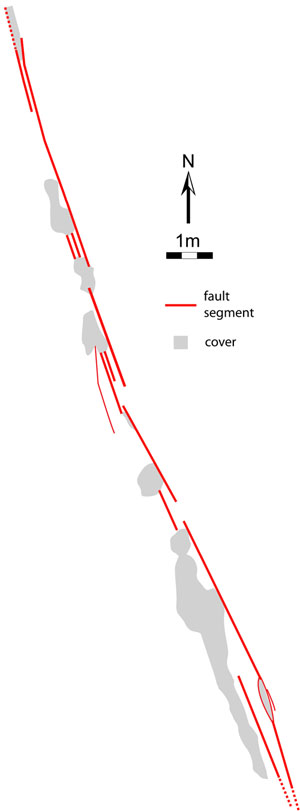
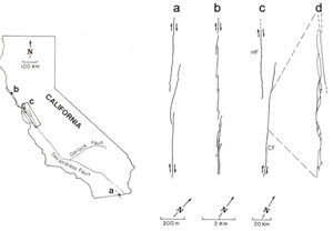
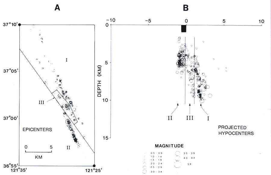
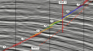
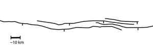
Fault traces in outcrops as well as in seismic sections across large regions are discontinuous, consisting of a number of segments at apparently every scale. Figure 1 shows an example of each fault type with multiple segments: (a) a left-lateral strike-slip fault with about 80 cm slip in sandstone, (b) a thrust fault with calcite filled pull-aparts between the neighboring segments, and (c) a series of normal fault segments in cross section. Figure 2 illustrates several examples of fault segmentation from the San Andreas plate boundary zone in increasing size. Images of strike-slip faults at depth are difficult to obtain in the absence of high resolution seismic data and reliable earthquake locations. Therefore, down-dip geometry of these faults and the geometry of their segments at depth are generally uncertain. However, there is little doubt that the geometric complexities mentioned above also occur at subsurface. Figure 3 shows a seismic image of a strike-slip fault system with distinct segments at subsurface. High resolution earthquake locations also indicate large scale discontinuities along strike-slip faults in down-dip direction.
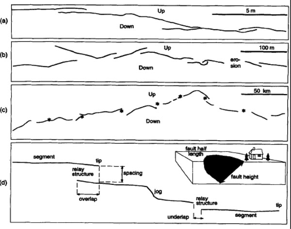
Dip-slip faults also have segments. Figure 4 illustrates a number of normal faults at various sizes with multiple segments and Figure 5 is a seismic dip line section showing an example of an array of normal fault segments from the Niger Delta. There are many mechanisms for fault segmentation. One is that, similar to opening mode fractures, faults may branch into segments as they grow. This notion is common in seismology in which the seismic signature of faults is believed to be generally simpler at depth than near the surface. Another is that vertical anisotropy such as alternating brittle-ductile units may cause vertically segmented faults. For example, the segmented normal fault array in Figure 6 was interpreted this way. One of the most common mechanisms for segmentation is inherited from the earlier structures whether they are opening, closing, or mixed mode structures. See the segmentation of joints and pressure solution seams for faults which form by shearing of these structures. Once started from different planes of weakness, fault interaction becomes the dominant factor for determining the ultimate echelon geometry of the segmented faults. See 'Fault interaction' for details.
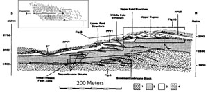
Similarly, both lateral and down-dip segmentation also occur in thrust faults as shown by Figure 6 and Figure 7.
It should be noted that there is also a trend opposite to the segmentation trend in fault growth such that a newer continuous fault may link previous segments thereby simplifying the fault geometry. This new, so-called 'through-going' fault forms by cataclastic deformation along already weakened zones of fragmented and comminuted rock material. See the section 'Growth of Faults by Linkage and Coalescence' for more information on this process. In the same manner, the length of fault segments and the size of the steps between them are observed to follow certain forms of distribution. See the sections 'Scaling between Fault Length and the Number of Segments per Unit Length' and 'Fault Segment Linkage.' | ||||||||||||
| Reference: |
||||||||||||
| Aydin, A., Nur, A., 1982 Aydin, A., Nur, A., 1985 Aydin, A., Schultz, R.A., 1990 Dahlstrom, C.D.A., 1969 de Joussineau, G., Aydin, A., 2007 de Joussineau, G., Aydin, A., 2009 Grant, N., 1990 Koledoye, B., Aydin, A., May, E., 2003 Myers, R., 1999 Myers, R., Aydin, A., 2004 Peacock, D.C.P., Sanderson, D.J., 1995 Reasenberg, P., Ellsworth, W.L., 1982 Willemse, E.J.M, 1994 Willemse, E.J.M, Pollard, D.D., Aydin, A., 1996 |
||||||||||||
|
Readme | About Us | Acknowledgement | How to Cite | Terms of Use | Ⓒ Rock Fracture Knowledgebase |
||||||||||||
