|
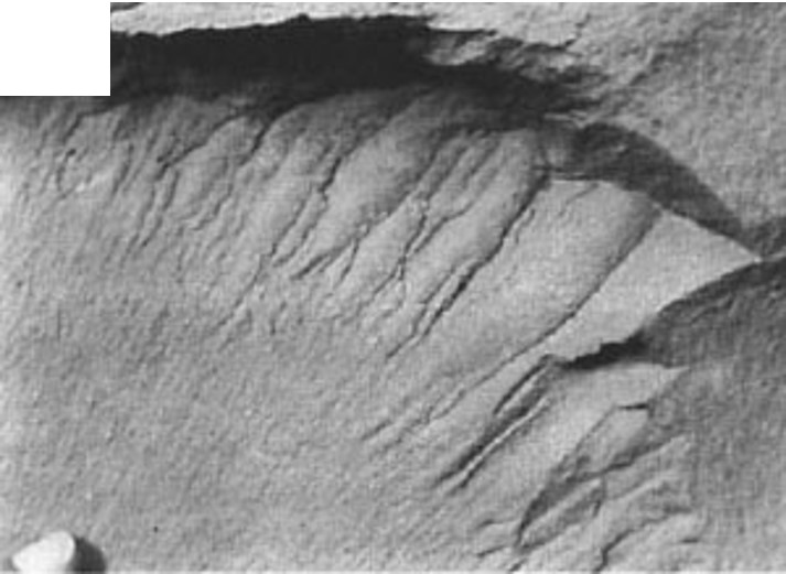
Hackle marks are surface morphology elements or features commonly observed on joint surfaces. Hackle marks (Figure 1 and Figure 2) are curvilinear boundaries with differential relief between adjacent surfaces, formed when a propagating joint front splits into unaligned partial fronts. Splitting of a crack front in rock may occur at an inhomogeneity, such as a void or inclusion, which locally modifies the stress field such that a crack front warps or splits to remain perpendicular to the maximum tension. Often, joint fronts are subjected to some shear stresses in mode-I and mode-II. Mixed mode I and II stresses result in breakdowns of the joint front.
 | | Figure 1. Photo showing curvilinear hackle marks on a joint surface, Watkins Glen, N.Y. See Helgeson and Aydin (1991) for other hackle mark images. |
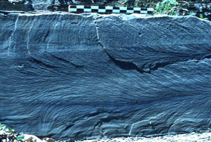
 | | Figure 2. Photo showing how several small hackles interact and link with each other. Finger tip at the bottom left for scale. From Pollard and Aydin (1988). |
Hackles either radiate from the origin or fan away from a curvilinear axis. Hackle marks are parallel to the local propagation direction. Hackles normally grow larger as they propagate, but in rare cases like that shown in Figure 3, they may recover to smooth propagation plane.
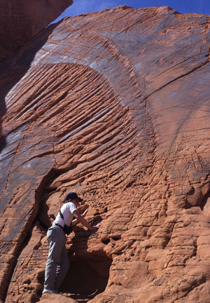 | | Figure 3. Photo showing joint surface features in sandstone, Valley of Fire State Park, NV. The hackle marks indicate a propagation direction from lower left to upper right. Note that there are two zones of radial breakdown separated by relatively smooth zones. This indicates that the multi-surfaces in the breakdown zones merge into a single smooth one. |
| |
Helgeson, D., Aydin, A., 1991. Characteristics of joint propagation across layer interfaces in sedimentary rocks. Journal of Structural Geology 13 (8): 897-911.
Pollard, D.D., Aydin, A., 1988. Progress in understanding jointing over the past century. Geological Society of America Bulletin 100 (8): 1181-1204.
|