| |||||||||||||||||||||||||||||||||
|
|
|||||||||||||||||||||||||||||||||
|
|
|||||||||||||||||||||||||||||||||
| Mechanisms and Mechanics of Columnar Joints | |||||||||||||||||||||||||||||||||
|
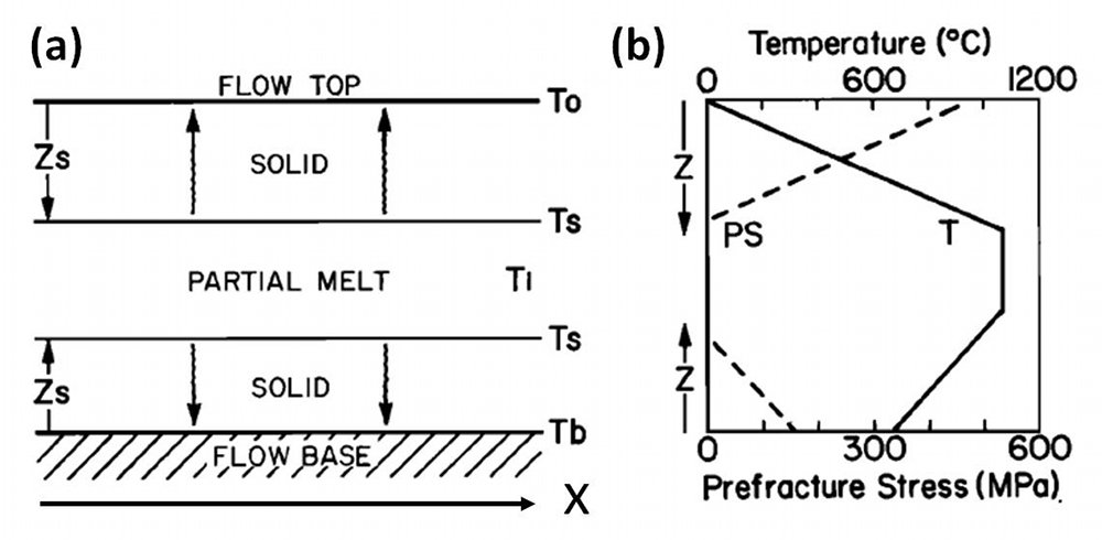
The driving force for thermal contraction fractures is thermal stresses produced by cooling of a magma body or drying of a mud layer. For a linear elastic material obeying Hooke's law σx = Eε, the thermal stress is linearly proportional to the change of temperature: σ∗x = αβ(ΔΤ) where σ∗ is the thermal stress in the x-direction and ε is the strain, ΔΤ is change of temperature, α is the thermal expansion coefficient, E Young's modulus, ν Poisson's ratio and β = E /(1−ν). The simplest way of conceptualizing the mechanical processes leading to thermal fracturing is to consider a conductive cooling of an elastic body from the top and the bottom (Figure 1a) resulting in a pre-fracture temperature and thermal stress distribution plotted in Figure 1b.
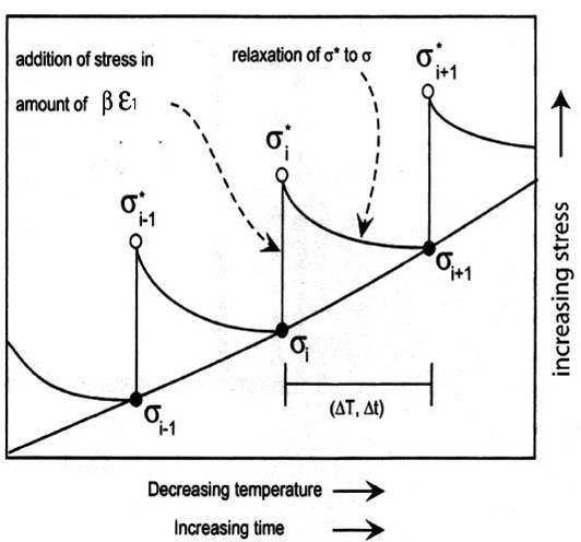
For a viscoelastic material using a Maxwell model (stress is related to the strain rate through viscosity), the thermal stress-strain relationship is given by ∂ε/∂t = (1/β) ∂σ/∂t + (1/η)σ, where η is the viscosity and includes the effect of temperature. Given a state of stress at a certain time (σι), the stress (σι+1) at a time step (ti+1) as shown schematically in Figure 2 can be calculated using the equation below:
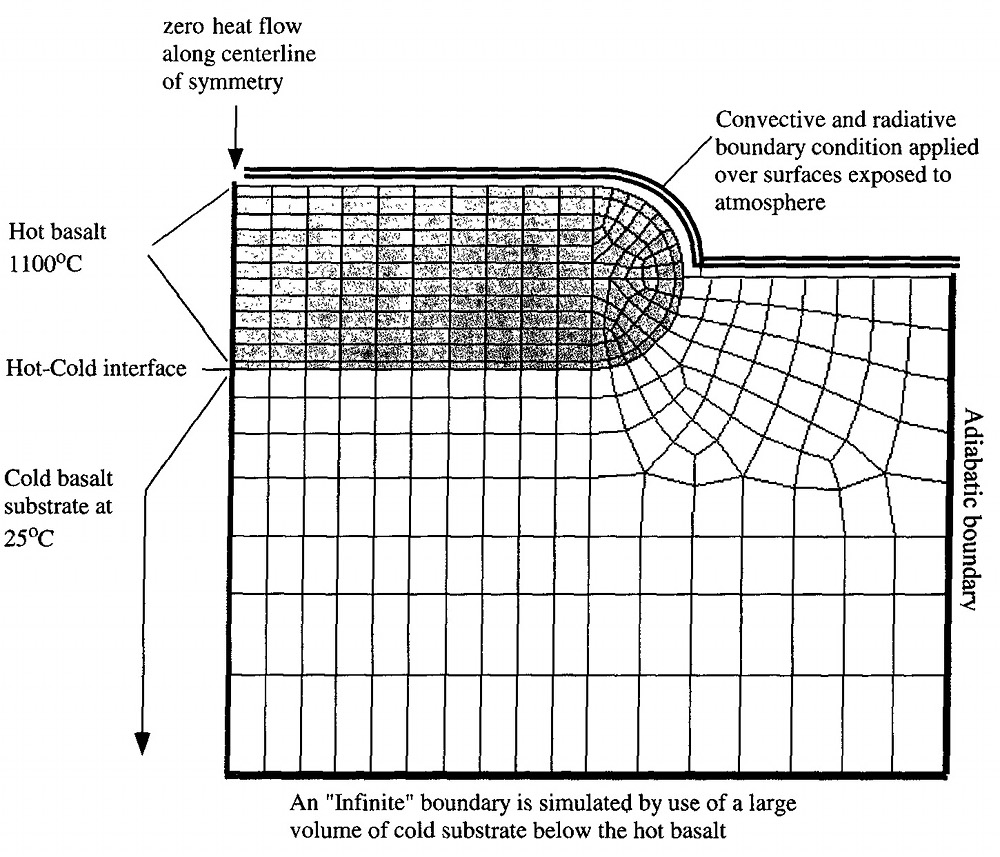
σt≥tι = [σι + ει (Ε/(1−ν))]Exp{-E (ti+1)/(1− ν)ηι} A more realistic configuration should include the flow ends (Figure 3) where the geometry is more complex than that assumed in Figure 1 and for a dissipative time-dependent rheology, requiring numerical solutions using FEM.
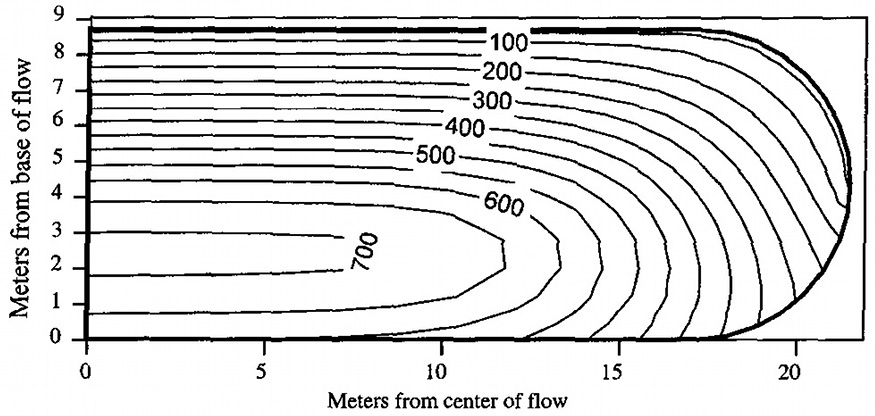
The temperature distribution in such a body 8.7 m thick and over 40 m wide after 380 days is calculated using ANSYS (see Lore et al., 2001 for details) incorporating heat loss by convection and radiation at the top surface and cooling by conduction at the base. The model also includes temperature dependent thermal conductivity as well as the latent heat released due to phase change from liquid magma to solid rock. Figure 4 shows profiles of the isotherms indicating faster cooling from the top surface where the atmospheric temperature is taken to be 0 °C than that of the base at the contact with the substrate of a higher temperature, for example, 25 °C. Without fracturing, this system would take over one year to completely solidify and would generate a stress distribution along parallel plates (zero being the top surface and 8.7 m being the base) as shown in Figure 5.
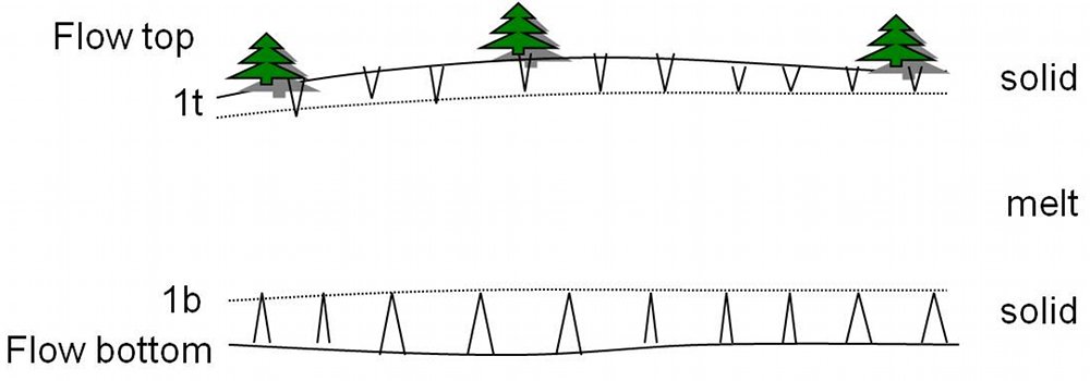
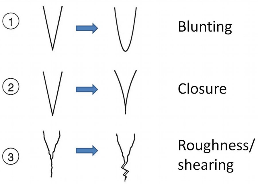
One of the most interesting aspects of the problem including fracturing in a dissipative system is the incremental or cyclic cooling and fracturing at discrete time steps. It turns out that cooling lava is capable of fracturing under a certain range of temperatures, generally 7500-8500 °C. Taking the lower value, when 7500 °C temperature is reached at the top and the base, the first thermal fracture arrays will form normal to the isotherms as illustrated schematically in Figure 6. However, partly due to the fracture tips meeting the melt at the central part, the initial fractures stop once the solid increment is traversed. It is thought that the fracture tips relax at the viscous melt causing blunting as shown in Figure 7, which reduces the stress concentration and retards the propagation until enough thermal stress builds up to drive the second increment of fracturing in the next solidified layer. Alternatively, a complete closure of the two surfaces on either side of the fracture tip area, or rough fracture surfaces with local shearing mode of deformation prevent a continuous fracture growth.
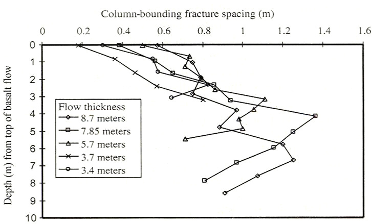
As shown by Lachenbruch (1962) and Nemat-Nasser et al. (1979), a fracture or joint normal to a surface relieves stress over a distance proportional to its height or the thickness of the brittle layer in which the fracture/joint occurs. It follows that there is a clear relationship between the thermal fracture height or the thickness of solidified layer increments and spacing of thermal fractures. Since the thickness of the layer solidified enough to fracture is inversely proportional to the cooling rate (-dT/dt), then the thermal fracture spacing is proportional to the inverse of the cooling rate (Figure 8). Using the temperature distribution in a flow with a known shape and thickness, it is possible to calculate the cooling rate and it is of course straightforward to measure the fracture spacing in the field. These are given for the 8.7 m flow which we use as an example in several links related to thermal fracturing in Figure 8. Lore et al. (2001) proposed that this can be used for predicting thermal fracture distributions for flows whose thicknesses and approximate geometry can be estimated.
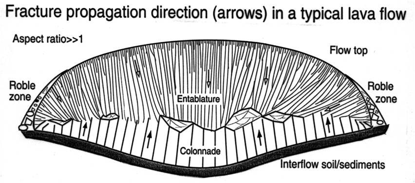
As conceptualized in Figures 1 through 5, thermal fractures initiated from the flow top and bottom propagate towards the interior as shown schematically in Figure 9 (see arrows). These domains are called entablature and colonnade and their heights can be estimated for a cooling regime modeled in Figures 2 to 4. Because of the faster cooling from the flow top than the base, the columns are slender and longer in the entablature. Also, due to the possibility of quenching by surface waters, which locally accelerates the cooling, there are more curvilinear and intersected or juxtaposed fractures there. Hence, at the meeting of the entablature and colonnade, which commonly occurs at about two thirds of the thickness from the top surface, irregular fracture orientations are common in part due to the interaction and intersection of various fracture systems.
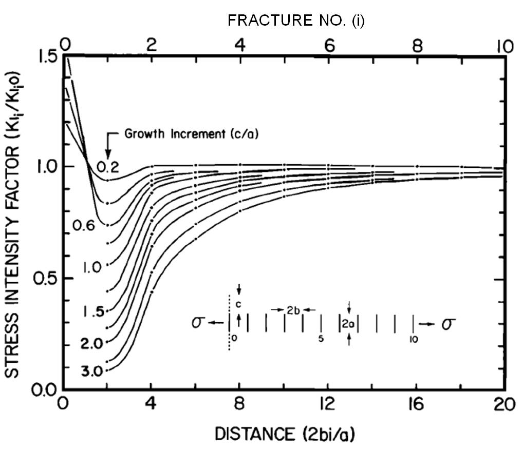
Another interesting aspect of thermal fracture evolution is the co-called fracture elimination due to the interaction of fractures in an array either starting from a flow top or flow bottom. The basic mechanics of this phenomenon can be seen from a simulation of fracture stress intensity associated with an array of parallel fractures with a spacing 'b' and a length 'a' in an elastic medium subjected to symmetric loading (Figure 10). If the fracture at the center is extended by an amount 'c,' then the normalized stress intensity at the tips of nearby fractures are reduced. This reduction is proportional to the amount of growth at the central fracture and inversely proportional with the distance from the growing fracture. Also see information on 'Joint Sets' and 'Joint Spacing.'
| |||||||||||||||||||||||||||||||||
| Reference: |
|||||||||||||||||||||||||||||||||
| DeGraff, J.M., Aydin, A., 1993 Lore, J., 1999 Lore, J., Aydin, A., Goodson, K., 2001 Nemat-Nasser, S., Oranratnachai, A., Keer, L.M., 1979 |
|||||||||||||||||||||||||||||||||
|
Readme | About Us | Acknowledgement | How to Cite | Terms of Use | Ⓒ Rock Fracture Knowledgebase |
|||||||||||||||||||||||||||||||||