Rock Fracture
KNOWLEDGEBASE
  

Growth of Columnar Joints

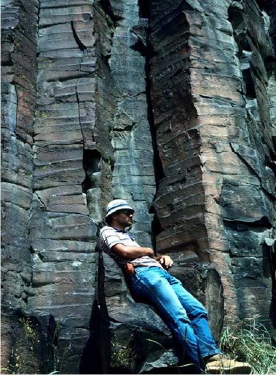
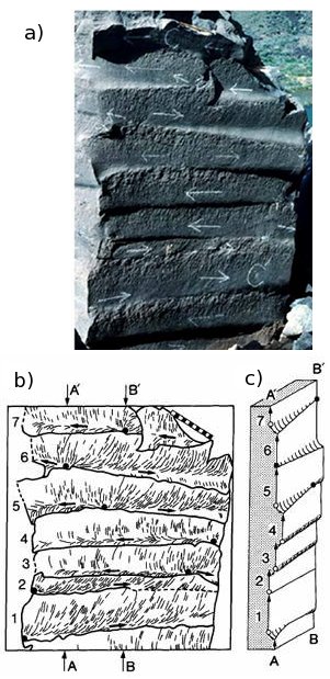
The growth of columnar joints is an incremental process as inferred from the morphology of the joint surface features commonly called striations (Figure 1).

A photograph showing a system of columnar joints in basalt exposed along the Boise River at Lucky Peak Dam, Idaho (Site 6 on the location map in Figure 2). Bands known as striations normal to the column axes are visible on the joint surfaces and represent joint growth increments. From DeGraff and Aydin (1987).Figure 1. A photograph showing a system of columnar joints in basalt exposed along the Boise River at Lucky Peak Dam, Idaho (Site 6 on the location map in Figure 2). Bands known as striations normal to the column axes are visible on the joint surfaces and represent joint growth increments. From DeGraff and Aydin (1987).

Each joint increment appears as a band representing a discrete fracturing cycle as recorded by an initiation point or origin, hackle marks indicating local propagation direction, and termination front or arrest line (Figure 2), the collection of which describes the temporal and spatial evolution of the growth of a polygonal joint system. The initiation points and the arrest lines of the adjacent segments reveal the vertical and lateral evolution of the system. Contrary to common perception, vertically adjacent segments are not generally connected along the entire tip lines of the older segments and the consecutive segments are not initially in the same plane. After starting from a point on the tip line of the previous segment, the newer segment propagates predominantly laterally along the edge of the previous segment beyond the tip line (Figure 2). However, the older segments guide the newer ones and maintain the overall verticality of column faces, albeit with slight adjustments in the orientation of the newer segments from one level to the next.

Outcrop photo (a), map (b), and oblique view diagram (c) of a column surface. Note the striations with details of the incremental growth features in (a). These include initiation points (full white circles) and lateral propagation directions (white arrows) of sequential increments. (b) Interpretation of the surface morphology of a joint face and the incremental growth segments recording its cyclic growth segments from the bottom to the top with numbers from 1 to 7. The origins (full black dots) and hackle marks (thin, short black lines) show local propagation direction. Black arrows on the plume axes show local propagation directions. c) Oblique view of joints on cutout section A-A’ and B’-B illustrating the relationships between the vertically sequential segments. Overhangs or ledges (short curved lines), plume axes (open circles), and vertical components of segment propagation (black arrows) are shown. From Degraff and Aydin (1987).Figure 2. Outcrop photo (a), map (b), and oblique view diagram (c) of a column surface. Note the striations with details of the incremental growth features in (a). These include initiation points (full white circles) and lateral propagation directions (white arrows) of sequential increments. (b) Interpretation of the surface morphology of a joint face and the incremental growth segments recording its cyclic growth segments from the bottom to the top with numbers from 1 to 7. The origins (full black dots) and hackle marks (thin, short black lines) show local propagation direction. Black arrows on the plume axes show local propagation directions. c) Oblique view of joints on cutout section A-A’ and B’-B illustrating the relationships between the vertically sequential segments. Overhangs or ledges (short curved lines), plume axes (open circles), and vertical components of segment propagation (black arrows) are shown. From Degraff and Aydin (1987).

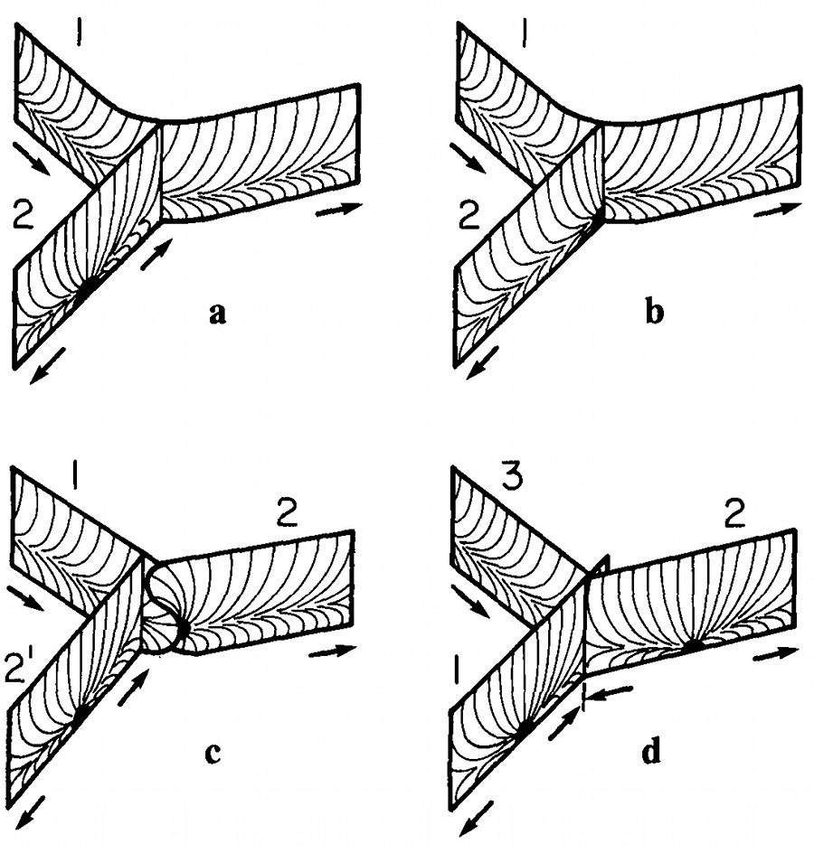
Each increment is also restricted in the lateral direction by the older neighboring fracture segments or column faces as illustrated in a series of diagrams in Figure 3. These diagrams show the kinematics of various types of lateral intersections at the so-called triple junctions. The orthogonal or T-intersections are no different than other orthogonal fracture types including the tectonic joints in sedimentary rocks. The non-orthogonal or Y-intersections which are more characteristic of thermal or desiccation fractures are commonly of two types: In the first, a segment terminates at a curvilinear fracture (3a) or emanates from it (3b), while the second includes three laterally intersecting segments with various intersection angles and relative ages (3c and d).

Lateral intersections of incremental fracture segments making up column faces: (a) A single fracture (2) terminating at a curvilinear fracture (1), (b) a single fracture initiating at a curvilinear fracture and emanating away from it, (c and d) three individual segments with a variety of intersection types. From Aydin and DeGraff (1988).Figure 3. Lateral intersections of incremental fracture segments making up column faces: (a) A single fracture (2) terminating at a curvilinear fracture (1), (b) a single fracture initiating at a curvilinear fracture and emanating away from it, (c and d) three individual segments with a variety of intersection types. From Aydin and DeGraff (1988).

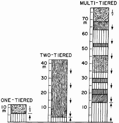
Based on the field data presented above and mechanical models to be presented under the link, 'Mechanisms and Mechanics of Thermal Fractures,' columnar joints are known to initiate from the outer boundaries (cooling surfaces) and propagate inward towards the interior in a cyclic fashion. If a flow is very thin, then only a single-tier column may be present (Figure 4). For moderately thick flows, two-tier columns are common, corresponding to dual vertical propagation direction and different cooling rates as described in other links related to columnar joints. Multi-tier columns are also present, especially in thick flows and those flows are subjected to variable cooling regimes due to the interplays between the geological and hydrological systems.

Single tier, two-tier, and multi-tier columns in lava flows. From DeGraff and Aydin (1987).Figure 4. Single tier, two-tier, and multi-tier columns in lava flows. From DeGraff and Aydin (1987).
Reference:

Aydin, A., DeGraff, J.M., 1988. Evolution of polygonal fracture patterns in lava flows. Science 239 (4839): 471-476.

DeGraff, J.M., Aydin, A., 1987. Surface morphology of columnar joints and its significance to mechanics and direction of joint growth. Geological Society of America 99 (5): 605-617.

DeGraff, J.M., Aydin, A., 1993. Effect of thermal regime on growth increment and spacing of contraction joints in basaltic lava. Journal of Geophysical Research - Solid Earth 98 (B4): 6411-6430.

Lore, J., Aydin, A., Goodson, K., 2001. A deterministic methodology for prediction of fracture distribution in basaltic multiflows. Journal of Geophysical Research - Solid Earth 106 (B4): 6447-6459.

Ryan, M.P., Sammis, C.G., 1981. The glass transition in basalt. Journal of Geophysical Research 86: 9519-9535.


Readme    |    About Us    |    Acknowledgement    |    How to Cite    |    Terms of Use    |    Ⓒ Rock Fracture Knowledgebase