Rock Fracture
KNOWLEDGEBASE
  

Multiple Normal Fault Sets

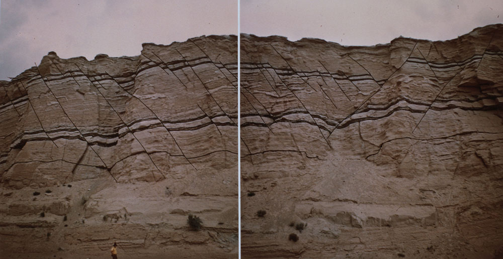
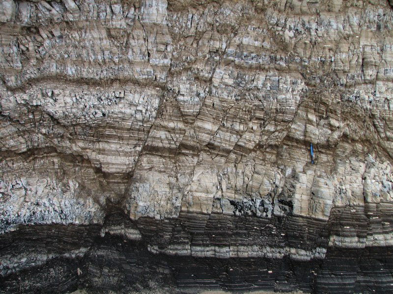
More than other fault types, multiple normal fault patterns are better known in the literature as well as in casual web sites on faulting. One of the reasons for these abundant examples of normal fault patterns is the fact that it is easier to recognize throws in sections in field exposures and in seismic images.

The first example of a normal fault network is in sandstone on a river bank (Figure 1). Thanks to a pair of mudstone layers at two levels, the fault traces are readily traceable (mapped on the photo mosaic) and the throws are easily measurable. The two sets make an intersection angle of about 60 to 70 degrees. Mutual abutting relationships (on the right panel) indicate that the two sets are contemporaneous. The second example occurs on a vertical cliff face of siliceous shale (Figure 2). Thin multi-colored beds show the fault traces and throws quite well.

Two sets of normal faults exposed on sandstone (brown) and shale (dark) beds of the Entrada Formation along a steep cliff on the northern side of the Freemont River near Hanksville, UT. The dip angle of both left- and right-dipping sets is about 55 degrees. Notice A. M. Johnson as scale at the bottom of the left panel. From Aydin (1973).Figure 1. Two sets of normal faults exposed on sandstone (brown) and shale (dark) beds of the Entrada Formation along a steep cliff on the northern side of the Freemont River near Hanksville, UT. The dip angle of both left- and right-dipping sets is about 55 degrees. Notice A. M. Johnson as scale at the bottom of the left panel. From Aydin (1973).
Two sets of normal faults with dihedral intersection angles on a vertical cliff face in the siliceous shale of the Monterey Formation exposed at Jalama Beach, central California coast.Figure 2. Two sets of normal faults with dihedral intersection angles on a vertical cliff face in the siliceous shale of the Monterey Formation exposed at Jalama Beach, central California coast.

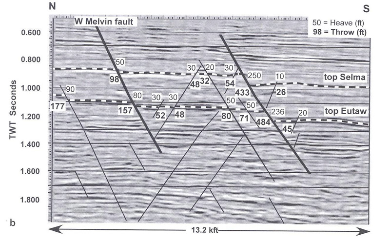
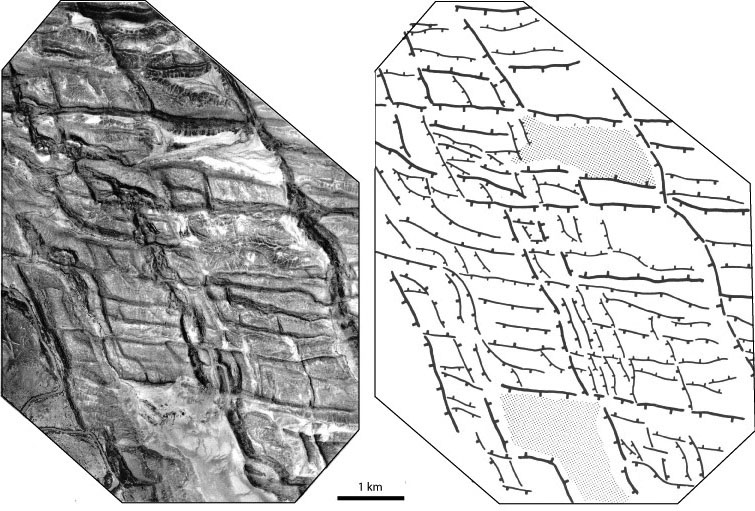
Figure 3 displays two normal fault sets in a seismic section. Two of the largest faults with throws of about 50 and 150 meters in the section were also detected by boreholes. Notice the spatial distribution of the N-dipping set of smaller faults between the more prominent S-dipping set making a ladder-like pattern. Multiple normal fault patterns with more than two sets occur in broadly deformed regions. Here we use two well-known rifts as an example. The picture-perfect pattern from Afar (Figure 4) displays hierarchical occurrence of two pairs of normal faults in two trace orientations and with mutual abutting relations. Each pair has two sets with opposite dip-direction. This pattern with orthorhombic symmetry is quite typical. For additional examples, please see the 'Multiple Shear Band Sets.'

The trace of two sets of conjugate normal faults in a seismic section across Gilbertown, Alabama. Faults with thicker lines were also identified by well data. Numbers indicate throw (bold) and heave (regular) which is horizontal throw. Note the abutting relationship between the two sets indicating how the sequential formation of the sets may control the spatial distribution of the faults. From Groshong (2006, 2nd ed.).Figure 3. The trace of two sets of conjugate normal faults in a seismic section across Gilbertown, Alabama. Faults with thicker lines were also identified by well data. Numbers indicate throw (bold) and heave (regular) which is horizontal throw. Note the abutting relationship between the two sets indicating how the sequential formation of the sets may control the spatial distribution of the faults. From Groshong (2006, 2nd ed.).
Photographic image and fault map of an area of the west central Afar Rift showing four sets of two pairs of normal faults in mutually abutting intersection geometry. Note the hierarchical lengths of the faults in both systems. From Kronberg, P. (1995).Figure 4. Photographic image and fault map of an area of the west central Afar Rift showing four sets of two pairs of normal faults in mutually abutting intersection geometry. Note the hierarchical lengths of the faults in both systems. From Kronberg, P. (1995).

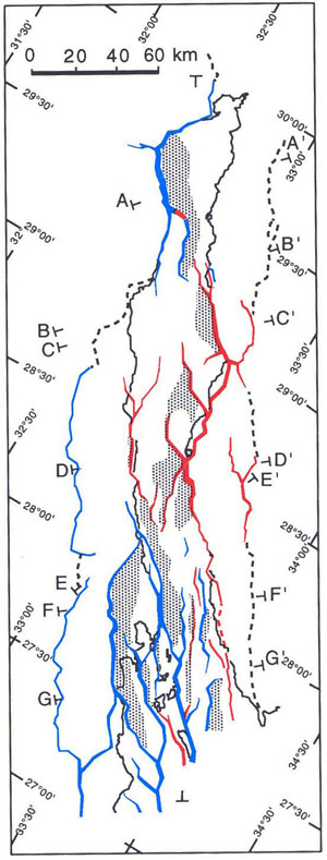
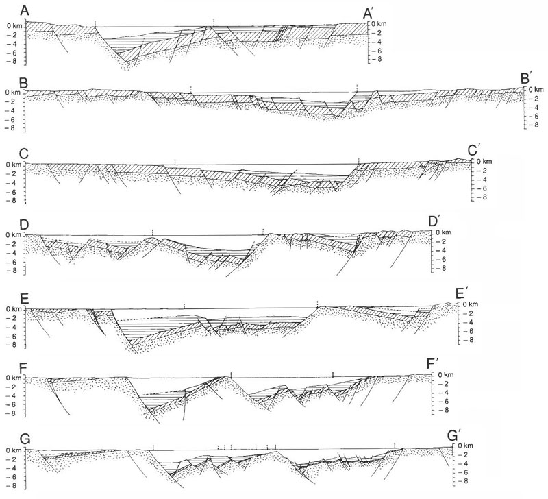
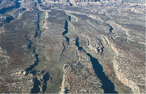
The other example is located on the eastern side of the Gulf of Suez displaying a more complex normal fault pattern with considerable spatial variation (Figure 5). In spite of this complex map pattern, the interpreted cross section patterns appear to be quite simple forming a series of horst and grabens (Figure 6). Horsts and grabens are structural highs and lows, respectively, which, under certain conditions controlled by erosional resistance of rock units, provide spectacular geomorphic scenes as shown in Figure 7 which is an aerial photograph of the Canyonlands in SE Utah.

A simplified pattern of normal faults in excess of 1 km of throw on the eastern side of the Gulf of Suez. Blue faults are down thrown to the NE, red faults are downthrown to the SW, and dashed lines are for the basin bounding faults. Stippled areas represent pre-Miocene surface below 4 km. The locations of a series of sections in Figure 7 are also marked. From Patton et al. (1994).Figure 5. A simplified pattern of normal faults in excess of 1 km of throw on the eastern side of the Gulf of Suez. Blue faults are down thrown to the NE, red faults are downthrown to the SW, and dashed lines are for the basin bounding faults. Stippled areas represent pre-Miocene surface below 4 km. The locations of a series of sections in Figure 7 are also marked. From Patton et al. (1994).
Serial cross sections across the Gulf of Suez showing how the patterns defined by the dip domains vary along and across the structure. From Patton et al. (1994).Figure 6. Serial cross sections across the Gulf of Suez showing how the patterns defined by the dip domains vary along and across the structure. From Patton et al. (1994).
Horst and graben structures in Canyonland National Park, Utah. From Eric H. Christiansen, Earth\\'s Dynamic System, Web Edition 1.0. http://earthds.info/pdfs/EDS_07.PDF.Figure 7. Horst and graben structures in Canyonland National Park, Utah. From Eric H. Christiansen, Earth\\'s Dynamic System, Web Edition 1.0. http://earthds.info/pdfs/EDS_07.PDF.

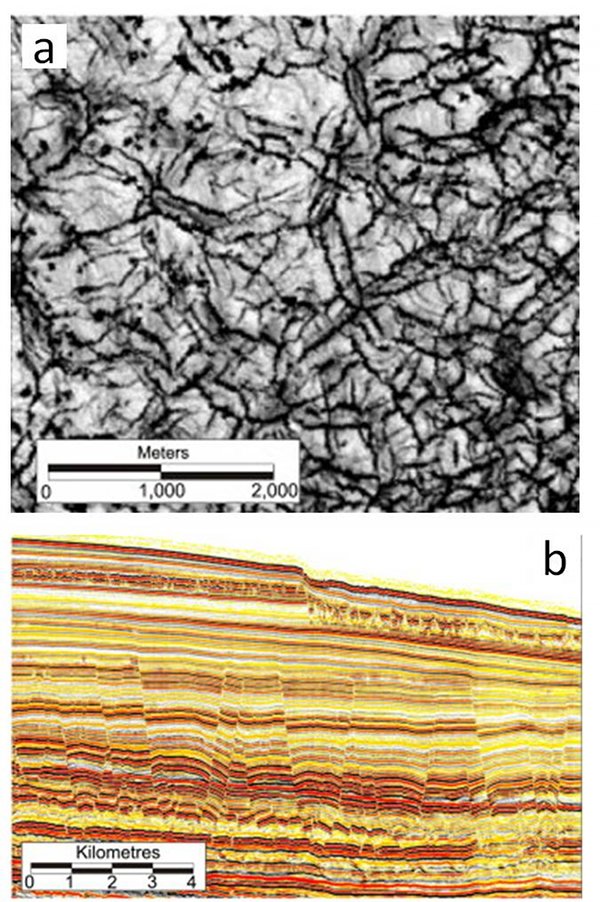
One of the most intriguing multiple sets of normal faults is that of the so-called polygonal fault systems occurring in fine-grained sediments (Figure 8). They often are confined within distinct sequences and their pattern varies as a function of their degree of development.

Polygonal fault systems in plan (a) and profile (b) views from offshore Norway. Notice that plan patterns range from rectangular to hexagonal and profile patterns are typically sequence bounded with various degrees of development. From Cartwright (2011).Figure 8. Polygonal fault systems in plan (a) and profile (b) views from offshore Norway. Notice that plan patterns range from rectangular to hexagonal and profile patterns are typically sequence bounded with various degrees of development. From Cartwright (2011).
Reference:

Aydin, A., 1973. Field study and theoretical analysis of some small faults in Montana, Wyoming and Utah. MS Thesis, Stanford University, 51 p.

Cartwright, J.A., 2011. Diagenetically induced shear failure of fine-grained sediments and the development of polygonal fault systems. Marine and Petroleum Geology 28: 1593-1610.

Christiansen, E.H., 2009. Earth's Dynamic System, Web Edition 1.0. http://earthds.info/pdfs/EDS_07.PDF.

Groshong, R.H., Jr, 2006. 3-D Structural Geology. Springer-Verlag, Heidelberg, 400 p. (2nd ed.).

Kronberg, P., 1995. Tektonische Strukturen in Luftbildern und Satellitenaufnahmen. Ferdinand Enke Verlag Stuttgart, 204 p.

Patton, T.L., Moustafa, A.R., Nelson, R.A., Abdine, S.A., 1994. Tectonic evolution and structural setting of the Suez rift. In: Landon S. M. (ed.) Interior Rift Basins. American Association of Petroleum Geologists, Memoirs 59: 956.


Readme    |    About Us    |    Acknowledgement    |    How to Cite    |    Terms of Use    |    Ⓒ Rock Fracture Knowledgebase