| ||||||||||||
|
|
||||||||||||
|
|
||||||||||||
| Mechanisms and Mechanics of Multiple Compaction Band Sets | ||||||||||||
|
The mechanics and mechanisms of multiple compaction band sets can be approached similar to those of opening mode fractures or joints. The fundamental difference is that here compaction bands are in closing mode, anti-cracks, or Localized Volume Reduction Structures. In this regard, the mechanisms and mechanics of multiple sets of Joints and Pressure Solution Seams are applicable to the formation and patterns of multiple sets of compaction bands. The orthogonal patterns of compaction bands and their mechanics are relatively straight forward. For those compaction band sets with intersection angles smaller than 90 degrees, one of them is likely to be a shear band or shear-enhanced compaction band. It is also possible that the sets formed at distinctly different times and the older one didn't deform much during the formation of the younger set due perhaps to diagenetic strengthening following their formation. To consider bands with intersection angles noticeably less than 90 degrees and both sets being reactive, see 'Splay Volumetric Bands.' However, there are reasons that the mechanics of compaction band multiple sets and their patterns maybe significantly different than those of the joints and pressure solution seams because compactive strain localization is of an inherently different failure process and is controlled by different laws. In addition, mediums prone to compactive strain localization may have significantly different petrophysical properties perhaps due to their depositional architecture. These issues have been consider by Deng and Aydin (2015) using a failure criterion widely used in engineering for failure analysis of anisotropic materials and it is presented in other places in this Knowledgebase. The notion is based on the strength anisotropy of compactive strain localization as a function of various boundary conditions and the degree of anisotrophy represented by a set of elastic properties. The source of the anisotrophy is primarily dune boundaries and cross beds and the texture of the granular medium (Deng et al., 2015). Figure 1 shows a plot summarizing the model results from this work. In essence, the authors propose that the occurrence and distribution of various compaction band sets and their distribution geometry in Aztec sandstone in Valley of Fire State Park can be better understood by taking this approach.
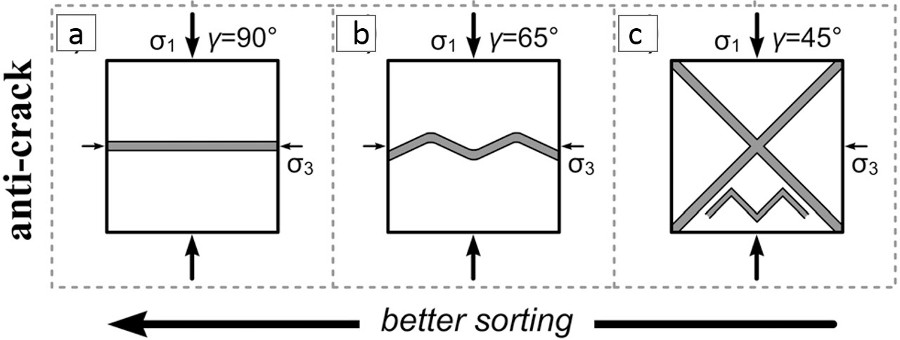
Liu et al., 2015(a), based on their petrographic analyses of thin section images of samples collected from the splay compaction bands of chevron, wavy, and straight geometry, suggested that the degree of sorting and porosity of the host rock increases from chevron to wavy to straight compaction bands. Using the inferred failure angles of band segments of the three band types (90°, 65°, and 45°), they proposed that the variation of band shape is due to the increasing failure angle of the sandstone (Figure 2), which is related to the increasing sorting and porosity.
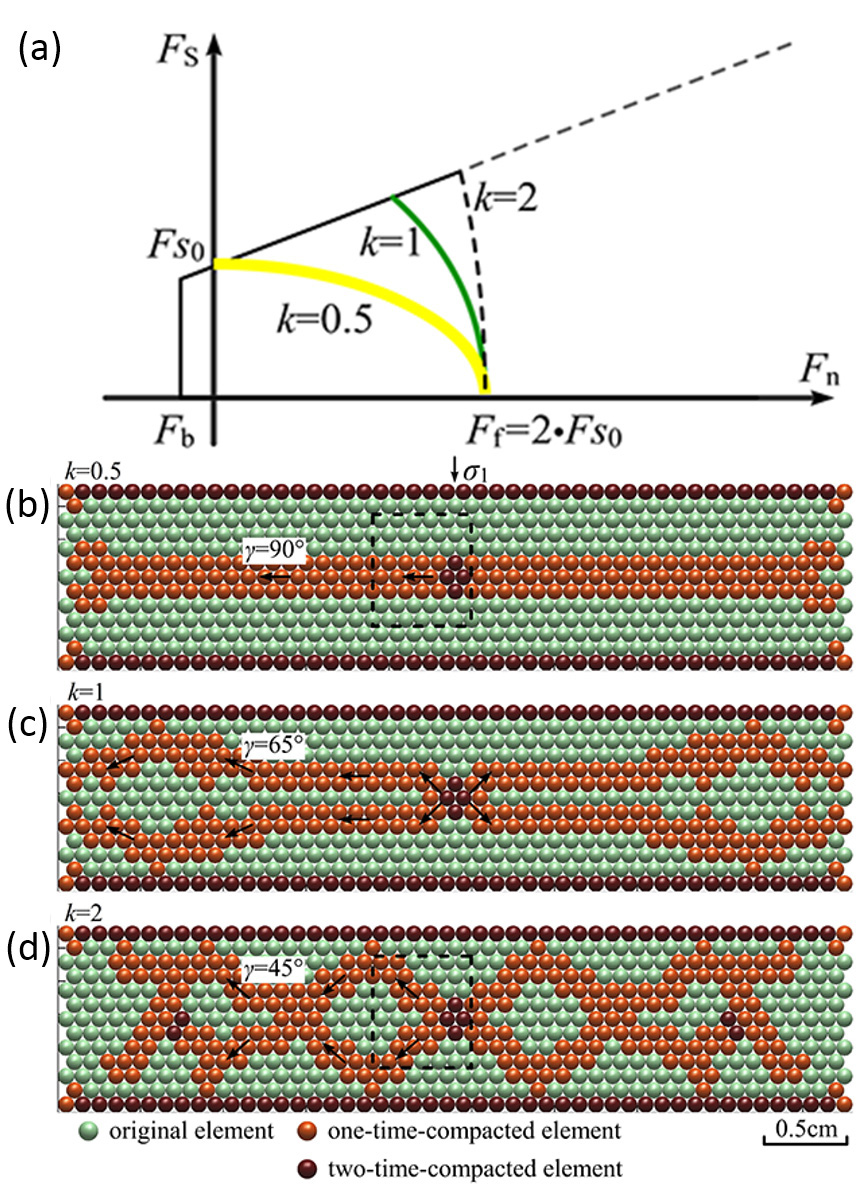
Liu et al., 2015(b), using a distinct element numerical method to simulate compaction band formation, concluded that wiggly compaction band geometry is controlled by the failure envelope or the critical yield stress (Figure 3a). They went on to conclude that the failure angle of compaction bands decreases from approximately 90° to 65° and 45° which roughly corresponds to the straight (Figure 3b), wavy (Figure 3c), and chevron (Figure 3d) compaction bands, respectively, as a function of the loading paths shown in Figure 3a.
There is little question that the formation and geometry of compaction bands are influenced by the petrophysical properties of the host rock as well as the stress paths as represented by the so-called Cap models, but the specific complex geometry of chevron and wavy compaction bands can only be fully understood by considering the interaction of two systems of compaction bands at high angle to each other and their propagation and interaction in space and time. The periodic switch of the segment orientation in chevron and wiggly bands requires such a complex scenario. | ||||||||||||
| Reference: |
||||||||||||
| Deng, S., Aydin, A., 2015 Deng, S., Cilona, A., Morrow, C., Mapeli, C., Liu, C., Lockner, D., Prasad, M., Aydin, A., 2015 Liu, C., Pollard, D.D., Gu, K., Shi, B., 2015 Liu, C., Pollard, D.D., Aydin, A., Deng, S., 2015 |
||||||||||||
|
Readme | About Us | Acknowledgement | How to Cite | Terms of Use | Ⓒ Rock Fracture Knowledgebase |
||||||||||||