|
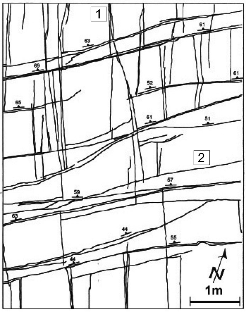
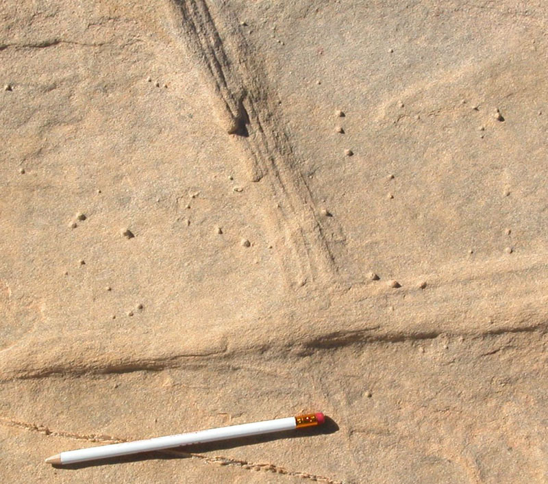
Compaction bands almost always occur in multiple sets. The simplest case is the one with two sets at right angle to each other or approximately so (Figure 1, Andrew Thomas, unpublished map). Then, they are said to be orthogonal. Mutual abutting of the members of each set against the members of the other set as shown in the map and the isolated close-up view (Figure 2) suggests that they formed concurrently in a geological sense although it is difficult to know the exact chronology by this method.
 | | Figure 1. Two sets of compaction bands in nearly orthogonal pattern and mutually abutting relationship on a pavement of Aztec Sandstone, Valley of Fire State Park, Nevada. Set 1 has a trace trending N-S with about 90 degree dip angle, while Set 2 has an average trace trending close to E-W with dip angles ranging from 44 degrees to 69 degrees. From Andrew Thomas, unpublished map. |
 | | Figure 2. A compaction band zone truncating at another one with a right angle in a pavement of Aztec Sandsone between the Rainbow Vista and the Silica Dome, Valley of Fire State Park, NV. |
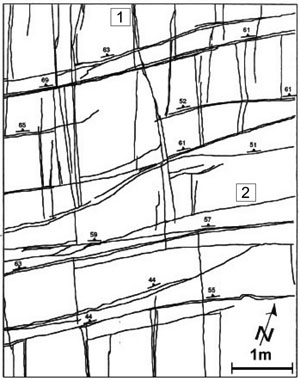
Figure 3 is a map by Hill (1989) showing at least three sets of compaction bands. Sets 1 and 2 are orthogonal and geologically contemporaneous based on their mutual cross-cutting relationship. Set 3 is the youngest with respect to the members of Set 1 and Set 2 to which they are connected. They commonly bisect the orthogonal sets in a general sense. They are contained between adjacent Set 1 bands or Set 2 bands. That is why Set 3 bands are generally shorter. They may be straight or planar, but commonly they have an irregular geometry which may be described as crooked, wiggly, wavy, or chevron. In some cases, a straight trace becomes crooked. Set 3 bands also have interesting relationships to the members of Set 1 and 2 bands which they intersect. Many Set 3 bands smoothly connected with the ends of some individual members or zones of the Set 1 or Set 2 bands (Figure 4). This may happen either by a band splaying off from another set or merging into another set as shown by curved trace geometry highlighted by lines with double arrowheads in the photograph in Figure 4a. This relationship between one of the orthogonal sets and members of Set 3 is shown in a closeup photograph in Figure 4b.
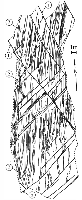 | | Figure 3. Trace map of multiple sets of compaction bands on a pavement of Aztec Sandstone exposed along the Cottonwood Wash, Valley of Fire State Park, Nevada. From Hill (1989). Hill identified two prominent orthogonal compaction band sets (marked as types 1 and 2) which are contemporaneous based on their mutually cross-cutting or abutting relationships. The members of the third set (marked 3) in about N-S trend are confined between the neighboring members of either one of the orthogonal sets and are crooked or wiggly. The spatial relationship indicates that the third set is relatively younger. However, based on the continuity of the members of the third set with either one of the members of the orthogonal sets (see for example, Figures 4 and 5), a significant overlap between the formation of the third set and the other two sets is evident, thus making them concurrent for certain periods of their development. |
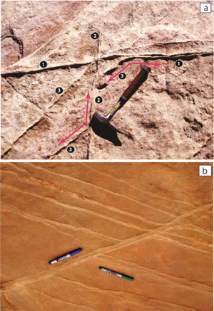 | | Figure 4. Intersection relationships among sets of compaction bands. (a) A photograph showing three sets of compaction bands; the older pair of two sets (marked as 1 and 2) and a relatively younger third set (marked as 3). (b) Photograph showing a series of compaction bands (marked by the green sharpie) splaying off of a zone of compaction bands (marked by the blue sharpie). The zone belongs to either one of the orthogonal sets (Set 1 or 2) while the individual bands splaying off belong to Set 3. |
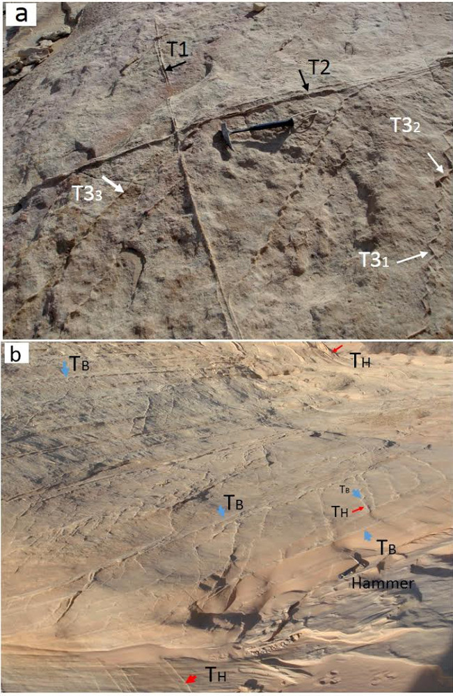
The chevron-like geometry of compaction bands made up of shorter segments parallel to each of the initial orthogonal sets as shown in figures 5a and b. Figure 5a shows two orthogonal sets at high-angle to bedding and segments of the third set trending diagonally on the average to the initial orthogonal sets. Figure 5b shows a sectional view in which the third set is made up of shorter segments parallel to either low-angle bed-parallel compaction bands or high-angle to bedding compaction bands. Recently Liu et al. (2015) described straight, wavy, and chevron compaction bands and the transition from straight to wavy and eventually to chevron geometry. These are discussed in 'Splay Volumetric Bands.'
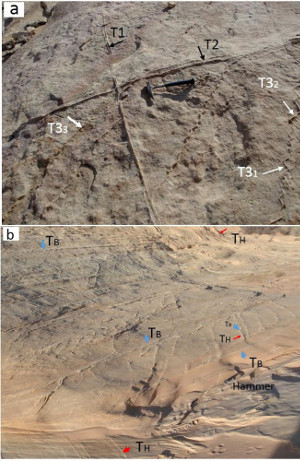 | | Figure 5. Multiple sets of compaction bands exposed at (a)Hill's area (Hill, 1989) and (b) Deng's area (Deng and Aydin, 2012).(a) Two orthogonal high-angle to bedding compaction bands (T1 and T2) and a third set (T3) made up of shorter segments sub parallel to the two orthogonal sets, Marked as T31 and T32, respectively. The third set also have other segments labeled as T33 which is straight and bisects the angle between the two orthogonal sets in outcrop. (b) Different than the previous view in (a), a sectional view shows a network of low-angle bed-parallel compaction bands (TB) and high-angle to bedding compaction bands (TH). In addition, similar to the case in (a) above, there is also a third set oblique to the bed-parallel and high-angle bends. Similar to T3 in (a), this set generally wiggly and each member has segments parallel to the bed-parallel and high-angle sets marked as TB and TH. |
Multiple sets of compaction bands and their distribution have closely linked to the architecture of the dunes in which they occur (Figure 6) as documented by Deng and Aydin (2012). These authors in another publication (Deng and Aydin, 2015) analyzed the occurrence of multiple compaction bands and their orientations in terms of the strength anisotropy of localized compaction. This topic is also discussed under 'Mechanisms and Mechanics of Multiple Compaction Bands.' For the impact of multiple compaction band sets and their distribution to fluid flow, see 'Porosity and Permeability of Compaction Bands' under 'Petrophysical Properties of Compaction Bands.'
 | | Figure 6. (a) Map showing distribution and orientation of compaction band multiple sets in the Aztec sandstone exposed in Valley of Fire State Park, Nevada. Different patterns are color coded and the dunes in which they occur are labelled as D1, D2, and so on and the cross bed orientations are also marked. (b) Schematic diagram showing domains of multiple compaction band multiple sets through the dunes D1, D2, and D6, approximately along the section A-B in Figure 6(a). Different multiple compaction bands are color-coded as identified below the diagram. The cross bed attitudes and the corresponding compaction band patterns are also shown. From Deng and Aydin (2012) and revised by the same authors. |
| |
Deng, S., Aydin, A., 2012. Distribution of compaction bands in 3D in an aeolian sandstone: The role of cross-bed orientation. Tectonophysics 574–575: 204–218. http://dx.doi.org/10.1016/j.tecto.2012.08.037.
Deng, S., Aydin, A., 2015. The strength anisotropy of localized compaction: A model for the role of the nature and orientation of cross-beds on the orientation and distribution of compaction bands in 3-D. Journal of Geophysical Research, Solid Earth 120: doi:10.1002/2014JB011689.
Hill, R.E., 1989. Analysis of deformation bands in the Aztec Sandstone, Valley of Fire State Park, Nevada. Master of Science thesis, University of Nevada, Las Vegas, 68p.
Liu, C., Pollard, D.D., Aydin, A., Deng, S., 2015. Mechanism of formation of wiggly compaction bands in porous sandstone: 1. Observations and conceptual model. Journal of Geophysical Research, Solid Earth 120: doi:10.1002/2015JB012372.
Sternlof, K.R., Chapin, J.R., Pollard, D.D., Durlofsky, L.J., 2004. Permeability effects of deformation band arrays in sandstone. American Association of Petroleum Geologists Bulletin 88 (9): 1315-1329.
|