Rock Fracture
KNOWLEDGEBASE
  

Echelon Faults

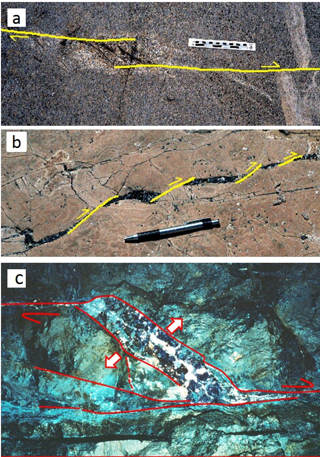
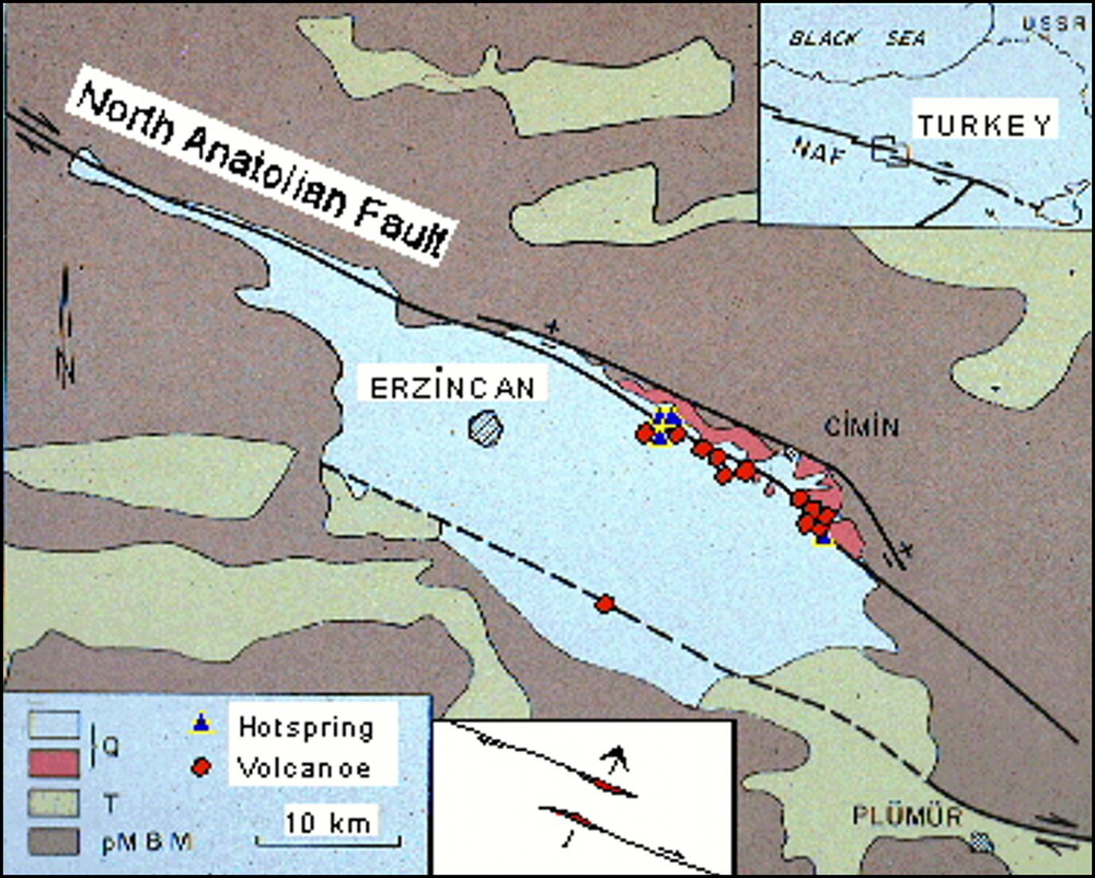
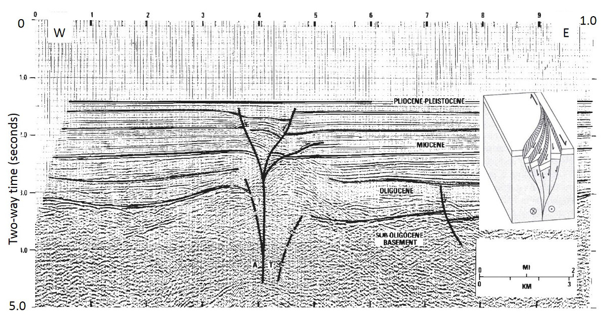
Faults are made up of strands and segments in all scales, as illustrated schematically under the link, 'Components of Faults.' These are responsible for most of the complexities associated with the development of faults in rocks and regions in all sizes. In fact, the science of studying faults would be extremely dull if natural faults had a continuous planar geometry without these complexities. Segments or neighboring faults can be co-linear, but often for a good reason, they are not aligned if the closer tips of the neighboring faults are near each other. As a result, echelon patterns of neighboring faults with a right sense or a left sense of steps, or stepovers with a certain amount of fault overlap are common in nature. 'Right' and 'left' are defined in a classical way: Standing on the trace of one and facing to the other on the right-hand or left-hand side, respectively. The geometry of echelon faults and the associated steps or relays can be better quantified in terms of the spacing (the distance between the faults perpendicular to their planes or traces) and the relative position of their tips with respect to each other (see the links 'Mechanisms and Mechanics of Echelon Faults' and 'Interaction of Faults'). Neighboring fault tips are rarely aligned along a line perpendicular to their plane or trace due to the mechanical interaction between the neighboring segments, which enhances the tendency of the tips to pass each other. In most cases, neighboring faults do overlap by a certain proportion of their lengths or heights, but underlapping fault geometries also exist. These are commonly called en echelon or, in short, echelon as used in this Knowledgebase.

Echelon fault geometry occurs in all major fault types, strike-slip and dip-slip or any kinematics in between although the orientation and type of accompanying structures may vary from one fault type to another. The accompanying structure types and their geometry also vary from one lithology to another or from one mechanical behavior to another. Here, an effort has been made to cover as many varieties as possible.

As a rule of thumb, it is practical to keep in mind that if the sense of stepping and slip kinematics are the same, the resulting deformation at the steps or relays is extensional. The results of this type are commonly referred to as extensional or divergent steps or pull-apart structures. On the other hand, if the senses of step and slip are opposite, then they are contraction or convergent steps or push-up structures. The first part of this section deals primarily with strike-slip faults because they are easy to observe in the field and therefore have plenty of good examples. The following part will focus on dip-slip faults in various lithologies to describe a broad range of structural behaviors and products.

Figure 1 includes a series of small size pull-apart structures: (a) veins filled by epidot (darker) in granitic rocks of Sierra Nevada, California; (b) rhomb-shaped dilation filled by tar in a detrital rock in coastal California, and (c) microscope view of a thin section showing a pull-apart filled by precipitated silica (quartz) and lead (galena) with a trace amount of silver from a sample from Topia Mine, Mexico. Examples of larger size pull-apart structures are also well-known. For example, Figure 2 is a map of the Erzincan pull-apart located at a right step along the right-lateral North Anatolian Fault in Turkey. Here, the structures of expression of the dilation within the basin are different: Normal faults, cinder cones, and dikes are wide spread especially along the northeastern boundary of the basin. Evidence for extensional deformation and the associated structures, particularly at the subsurface, can be better seen in seismic sections across pull-apart basins. Figure 3 shows an interpretation from rather old seismic data showing a profile across the Andaman Sea Fault in Indonesia. This type of fault patterns is commonly called a 'flower' structure in the industry; 'positive' if the faults have extensional component in a divergent step.

Photographs illustrating rhomb-shaped dilations filled by (a) veins in granitic rocks of Sierra Nevada, California; (b) hydrocarbon solidified into tar in the siliceous rock of the Monterey Formation in coastal California; (c) lead and silver (in addition to quartz) precipitation.Figure 1. Photographs illustrating rhomb-shaped dilations filled by (a) veins in granitic rocks of Sierra Nevada, California; (b) hydrocarbon solidified into tar in the siliceous rock of the Monterey Formation in coastal California; (c) lead and silver (in addition to quartz) precipitation.
Erzincan pull-apart basin along the right-lateral strike-slip North Anatolian Fault in Turkey. Volcanic cinder cones, dikes, lava flows, and hot springs are expressions of dilational deformation in the basin. From Ketin (1969).Figure 2. Erzincan pull-apart basin along the right-lateral strike-slip North Anatolian Fault in Turkey. Volcanic cinder cones, dikes, lava flows, and hot springs are expressions of dilational deformation in the basin. From Ketin (1969).
Seismic section across the Andaman Sea strike-slip fault zone showing interpreted fault segments with generally normal slip component accommodating localized extension. From Harding et al. (1985).Figure 3. Seismic section across the Andaman Sea strike-slip fault zone showing interpreted fault segments with generally normal slip component accommodating localized extension. From Harding et al. (1985).

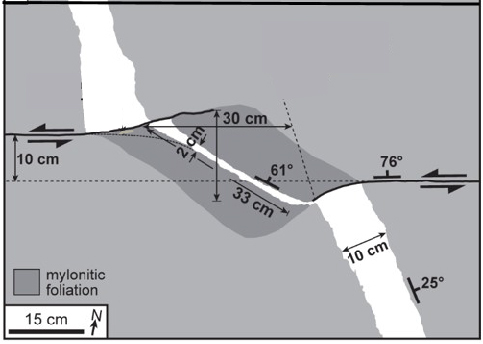
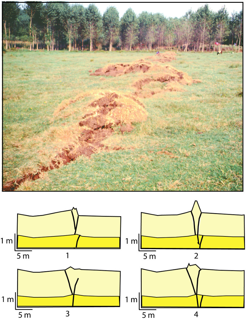
If the deformation is of contraction or compressional type in a fault step or relay, it is known as a contraction or compressional step or relay. Figure 4 is a map showing deformation of a segment of an aplite dike located within a step between a left-stepping echelon fault pair in granodiorite of Sierra Nevada, California. The thickness of the dike outside of the step is about 10 cm, but it has been reduced to about 2 cm within the step. Here, the structure accommodating the shortening is mylonitic foliation and the deformation mechanism was proposed to be plastic or elastoplastic. Figure 5 shows a series of left-steps marked by noticeable uplift of a previously flat field along the right-lateral North Anatolian Fault rupture near Izmit during the 1999 earthquake. For an obvious reason, these are referred to as push-ups or mole-tracks in the strike-slip literature. The cross sections below the photograph are projections of possible segment geometries into the subsurface.

Map showing contraction deformation of an aplite dike located between a pair of left stepping right-lateral faults in granodiorite exposed at the Sierra Nevada, California (Nevitt et al., 2014). The authors proposed that an elastoplastic rheology of Von Mises type in their model studies best matches their observation.Figure 4. Map showing contraction deformation of an aplite dike located between a pair of left stepping right-lateral faults in granodiorite exposed at the Sierra Nevada, California (Nevitt et al., 2014). The authors proposed that an elastoplastic rheology of Von Mises type in their model studies best matches their observation.
A series of push-up structures known as 'mole tracks' associated with the surface rupture of the North Anatolian Fault near the town of Izmit, western Turkey. Geological sections across each of these show the amount of local uplift and thrusting on the bounding faults. The average right-lateral slip along the rupture at this locality was about 4 m while the maximum uplift was about 80 cm. From Aydin and Kalafat (2002).Figure 5. A series of push-up structures known as 'mole tracks' associated with the surface rupture of the North Anatolian Fault near the town of Izmit, western Turkey. Geological sections across each of these show the amount of local uplift and thrusting on the bounding faults. The average right-lateral slip along the rupture at this locality was about 4 m while the maximum uplift was about 80 cm. From Aydin and Kalafat (2002).

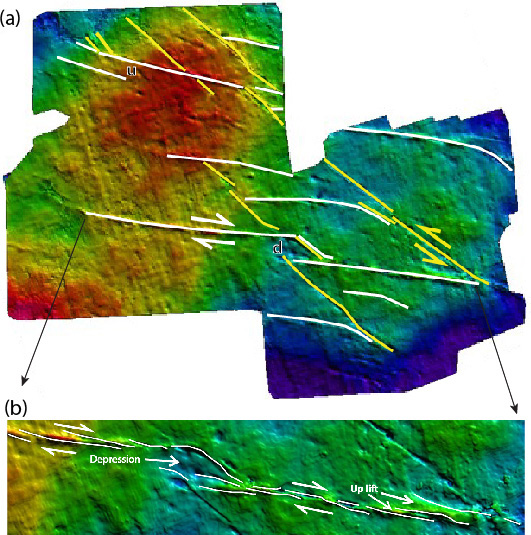
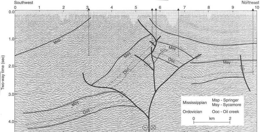
Structural depressions associated with extension and uplifts associated with contraction are best expressed in seismic data showing horizon maps and can be used for inferring the sense of the motion along segmented faults dominated by lateral-slip component. Figures 6a and b illustrate obvious depression (d) and uplift (u) at right-step and left-step, respectively, consistent with a right-lateral interpretation of an N75W fault set in a seismic data set from Abu Dhabi. Figure 6(b) is an enlargement of one of the faults showing finer scale steps with general uplift at the stepovers. Figure 7 shows a large scale example of an uplift or push-up structure in a seismic image from the Ardmore basin, Oklahoma, which was interpreted to be a basement involved convergent step or a negative flower structure as shown by the inset diagram. Note that the nearly vertical major strike-slip fault traces are not aligned indicating that the echelon patterns also occur in down dip direction. It suffices to point out that, in this case, the geometry and kinematics of the linkage products are different than those of the strike-slip faults with lateral steps.

Seismic images of a network of faults as they appear at the top of the Thamama Formation across a N-NE trending anticline, Abu Dhabi, UAE (Johnson et al., 2005). Two sets of faults (yellow in N45W and white in N75W orientations) were identified by the authors and interpreted as left- and right-lateral, respectively. Two relatively large steps with depression (d) and uplift (u) are pointed out in (a) and a series of other segments can be seen in (b). Some of the intersection relationships in (a) and the finer segments in (b) are our interpretations.Figure 6. Seismic images of a network of faults as they appear at the top of the Thamama Formation across a N-NE trending anticline, Abu Dhabi, UAE (Johnson et al., 2005). Two sets of faults (yellow in N45W and white in N75W orientations) were identified by the authors and interpreted as left- and right-lateral, respectively. Two relatively large steps with depression (d) and uplift (u) are pointed out in (a) and a series of other segments can be seen in (b). Some of the intersection relationships in (a) and the finer segments in (b) are our interpretations.
Seismic image and interpretation of a basement-involved push-up structure in the Ardmore Basin, Oklahoma. From Harding and Lowell (1979).Figure 7. Seismic image and interpretation of a basement-involved push-up structure in the Ardmore Basin, Oklahoma. From Harding and Lowell (1979).

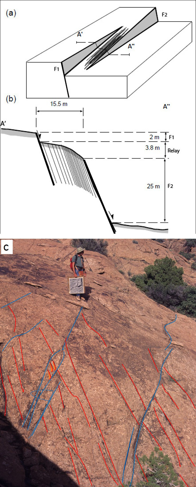
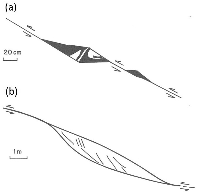
The next series of figures represents some select examples of dip-slip faults of dominantly normal or thrust kinematics with a variety of echelon patterns in a variety of lithologies. Figures 8a and b show a block diagram and a section, respectively, of echelon normal faults and the associated lateral relay between them in sandstone over a body of salt withdrawal at Arches National Park, Utah. The relay has been tilted by a series of shear band faults accommodating a total of about 4 m down-dropping across a distance of about 16 m between the bounding echelon faults marked by distinct slip surfaces with 2 and 25 m slip, respectively, along the scanline. Although the schematic section shows shear bands parallel the bounding faults within the ramp, there exist also shear band faults dipping in the opposite direction at normal fault relays as shown in Figure 8c. Figure 9 is a schematic diagram based on the observation of a mine shaft wall in a gold mine in South Africa. Here, in contrast to the cases in Figures 8a, b, and c, the diagonal relay fractures are joints and sheared joints.

A lateral relay bounded by two echelon segments of a normal fault at the northern flank of Cache Valley along the western trail to the Delicate Arch at Arches National Park, Utah. (a) Block diagram, (b) section showing the ramp topography produced by a series of shear band faults, (c) photograph of a relay containing a second set of normal faults dipping the opposite direction. Blue lines are fault traces parallel to the echelon faults and red lines are the second set of normal faults between the normal faults of the first set. Marco Antonellini as a scale. From Antonellini and Aydin (1995).Figure 8. A lateral relay bounded by two echelon segments of a normal fault at the northern flank of Cache Valley along the western trail to the Delicate Arch at Arches National Park, Utah. (a) Block diagram, (b) section showing the ramp topography produced by a series of shear band faults, (c) photograph of a relay containing a second set of normal faults dipping the opposite direction. Blue lines are fault traces parallel to the echelon faults and red lines are the second set of normal faults between the normal faults of the first set. Marco Antonellini as a scale. From Antonellini and Aydin (1995).
Diagram showing structures at the relays of a series of normal faults in a gold mine in South Africa. Fault zones of this nature are known to be at least 30 m long posing a major source of damage in the mining procedures. From McGarr et al. (1979).Figure 9. Diagram showing structures at the relays of a series of normal faults in a gold mine in South Africa. Fault zones of this nature are known to be at least 30 m long posing a major source of damage in the mining procedures. From McGarr et al. (1979).

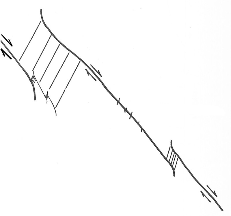
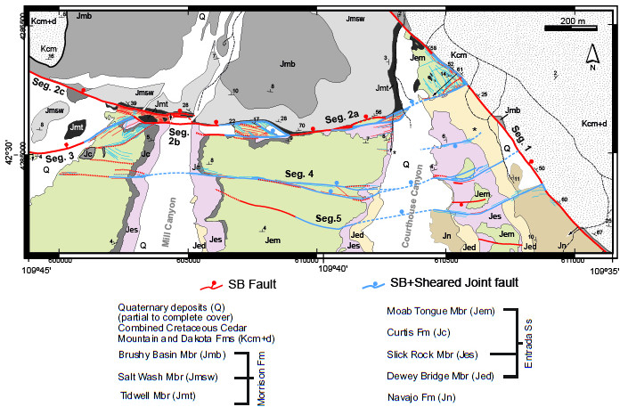
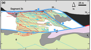
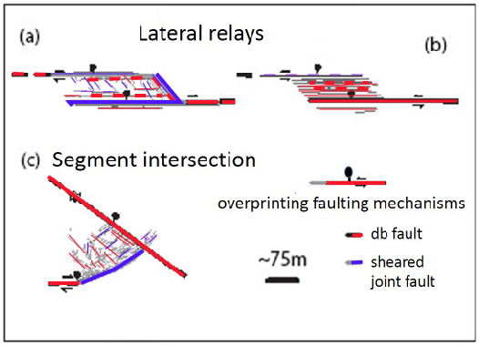
A series of more complex relay structures are well-exposed along the Moab Fault in Utah (Figure 10 and Figure 11), which is well known for its prototypical architecture. In this case, the additional complexity arises from the fact that two rather different types of failure structures occur in the Wingate and the Navajo sandstones as shear bands and sheared joints at the relays. Some of these structures and the associated deformation events show clear sequential age relationships as idealized in a simple schematic diagram in Figure 12, and may be related to a small component of shearing of opposite sense across the echelon fault segments.

Map of the Moab Fault, southeast Utah, showing major fault segments and several relays. The fault has about 900 m throw to the east of the map location. From Davatzes et al. (2005). See the next figure for the details of the relay in the middle.Figure 10. Map of the Moab Fault, southeast Utah, showing major fault segments and several relays. The fault has about 900 m throw to the east of the map location. From Davatzes et al. (2005). See the next figure for the details of the relay in the middle.
Details of one of the lateral relays shown in Figure 9. It shows structures formed from different failure types overprinting each other. From Davatzes et al. (2005).Figure 11. Details of one of the lateral relays shown in Figure 9. It shows structures formed from different failure types overprinting each other. From Davatzes et al. (2005).
Summary of the relay types and the associated structures along the Moab Fault, Utah. From Davatzes et al. (2005), but this particular collection not included in the manuscript.Figure 12. Summary of the relay types and the associated structures along the Moab Fault, Utah. From Davatzes et al. (2005), but this particular collection not included in the manuscript.

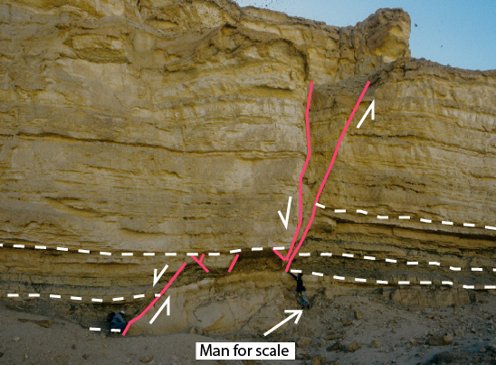
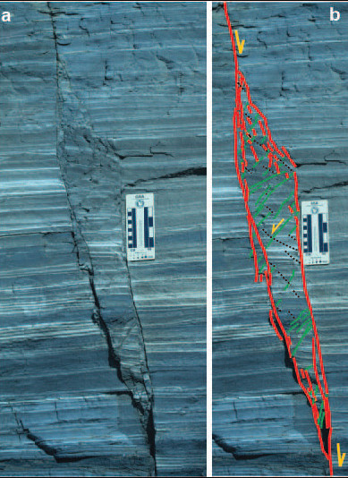
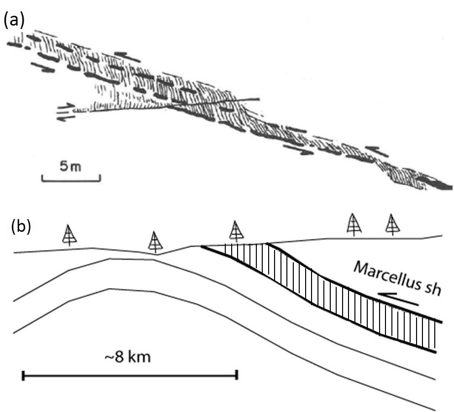
Figure 13 shows a contraction relay exposed on a steep cliff offsetting a limestone-shale unit for about 2 m in a normal sense on a steep dry river bank or wadi at Hadahid region of the Gulf of Suez, Egypt. The contraction or thinning of the limestone-shale horizon was accommodated by smaller normal faults in limestone and by cleavages within the shale. Figure 14a is a photograph showing a down-dip contraction relay between echelon normal faults in the siliceous shale of the Monterey Formation. In this case, the contraction has been accommodated primarily by two sets of faults color-coded as green and black in Figure 14b.

A normal fault with a contractional step in the Gulf of Suez. The throw is about 2 m. The shale unit at the bottom of the two units identified by dashed white lines shows significant reduction of thickness within the step suggesting that either the shale there contracted significantly or some shaly material extruded into the adjacent areas. From Younes and Aydin (1998).Figure 13. A normal fault with a contractional step in the Gulf of Suez. The throw is about 2 m. The shale unit at the bottom of the two units identified by dashed white lines shows significant reduction of thickness within the step suggesting that either the shale there contracted significantly or some shaly material extruded into the adjacent areas. From Younes and Aydin (1998).
Contractional deformation accommodated by multiple sets of faults in siliceous shale of the Monterey Formation near Lampoc, California. Photo and map by A. Aydin.Figure 14. Contractional deformation accommodated by multiple sets of faults in siliceous shale of the Monterey Formation near Lampoc, California. Photo and map by A. Aydin.

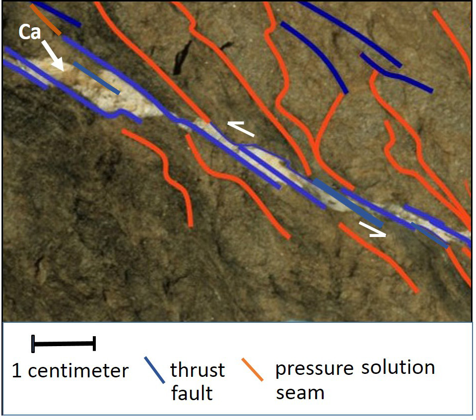
Figure 15 to Figure 17 are examples of various relays between thrust faults of various sizes. The pull-apart structures in Figure 15a and Figure 16 are filled by precipitants, while contraction was accommodated by faults and pressure solution seams or cleavages in the units dominated by shale.

(a) Pull-apart opening filled by calcite in limestone, Swiss Alps, and (b) a contraction relay in limestone at the entrance of the Smoky Mountains National Park, Tennessee. From Aydin (1988).Figure 15. (a) Pull-apart opening filled by calcite in limestone, Swiss Alps, and (b) a contraction relay in limestone at the entrance of the Smoky Mountains National Park, Tennessee. From Aydin (1988).
Pull-apart openings filled by calcite (Ca) between echelon thrust faults at low angle to bedding. Also present are cleavages at the contraction sides of the faults. Bays Mountain, Tennessee. For more details, see Ohlmacher and Aydin (1995).Figure 16. Pull-apart openings filled by calcite (Ca) between echelon thrust faults at low angle to bedding. Also present are cleavages at the contraction sides of the faults. Bays Mountain, Tennessee. For more details, see Ohlmacher and Aydin (1995).
(a) A series of cleavage duplexes formed at relays between bed-parallel thrust faults with large overlaps. (b) Large scale section showing the Marcellus Shale depicted to be deformed primarily by cleavages. From Nickelson and Cotter (1983) and Aydin (1988). This version is from Aydin (2014).Figure 17. (a) A series of cleavage duplexes formed at relays between bed-parallel thrust faults with large overlaps. (b) Large scale section showing the Marcellus Shale depicted to be deformed primarily by cleavages. From Nickelson and Cotter (1983) and Aydin (1988). This version is from Aydin (2014).
Reference:

Antonellini, M., Aydin, A., 1995. Effect of faulting on fluid flow in porous sandstones: Geometry and spatial distribution. American Association Petroleum Geologists Bulletin 79: 642–671.

Aydin, A., 1988. Discontinuities along thrust faults and the cleavage duplexes. Geological Society of America Special Publication 222: 223–232.

Aydin, A., Kalafat, D., 2002. Surface Ruptures of the August 17 and November 12, 1999, Izmit, and Duzce Earthquakes in NW Anatolia, Turkey: Their Tectonic and Kinematic Significance and the Associated Damage. Seismological Soc. Am. Bulletin 92: 95-106.

Aydin, A., 2014. Failure modes of shale and their implications for natural and man-made fracture assemblages. American Association of Petroleum Geologists Bulletin 98.

de Joussineau, G., Aydin, A., 2007. The evolution of the damage zone with fault growth in sandstone and its multiscale characteristics. Journal of Geophysical Research 112: B12401, doi:10.1029/2006jb004711.

Harding, T.P., Lowell, J.D., 1979. Structural styles, their plate tectonic habitats, and hydrocarbon traps in petroleum provences. American Assoc. Petroleum Geol. Bull. 63: 1116-1058.

Harding, T.P., Vierbuchen, R.C., Christie-Blick, N., 1985. Structural styles, plate-tectonic settings, and hydrocarbon traps of divergent (transtensional) wrench faults. In: Biddle, K.T., and Christie-Blick, N. (eds.), Strike-slip deformation, basin formation, and sedimentation. Society of Economic Paleontologists and Mineralogists Special Publication, no. 37, p. 35-45.

Harris, R.A., Day, S.M., 1999. Dynamic 3D simulations of earthquakes on en echelon faults. Journal of Geophysical Research 26 (14): 2089– 2092.

Ketin, I., 1969. Kuzey Anadolu Fayi hakkinda. Maden teknik Arama Enst. Dergisi 72: 1-27.

McGarr, A., Pollard, D.D., Gay, N.C., Ortlepp, W.D., 1979. Observations and analysis of structures in exhumed mine-induced faults. U.S. Geological Survey Open File Report 79-1239: 101–120.

Nevitt, J., Pollard, D.D., Warren, J., 2014. Evaluation of transtension and transgression within contractional fault steps: Comparing kinematic and mechanical models with field data. Journal of Structural Geology 60: 55-69.

Nickelsen, R.P., Cotter, E., 1983. Silurian depositional history and Alleghanian deformation in the Pennsylvania Valley and Ridge. Guidebook for the 48th Annual Field Conference of Pennsylvania Geologists, 192 p.

Ohlmacher, G., Aydin, A., 1995. Progressive deformation and fracture patterns during foreland thrusting in the Southern Appalachians. American Journal of Science 295 (8): 943-987.

Younes, A.I., Aydin, A., 1998. Gulf of Suez Field Trip Guidebook. The Stanford Shale Smear Project 1998 Field Trip Guide. Stanford Digital Repository. Available at: http://purl.stanford.edu/jp025yc8745.


Readme    |    About Us    |    Acknowledgement    |    How to Cite    |    Terms of Use    |    Ⓒ Rock Fracture Knowledgebase