Rock Fracture
KNOWLEDGEBASE
  

Mechanisms and Mechanics of Multiple Normal Fault Sets

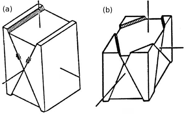
We have briefly referred to Anderson's conceptual and theoretical models of the three major fault types and their so-called conjugate patterns in two different sections: 'Multiple Fault Sets' and 'Andersonian and Mohr-Coulomb Theory of Faulting.' The issues regarding the number of fault sets and their intersection angles have been extensively discussed in the literature. It is straightforward to show that the conjugate faults can only accommodate two dimensional strain (or plane strain) neglecting the strain within the blocks between the faults. That is, one of the principal strain components coincides with the direction containing the intersection line of the two sets and represents a no-strain axis. For example, for the normal faults, the plane strain configuration is illustrated in Figure 1(a).

Diagrams showing idealized normal fault patterns corresponding to the plane (A) and 3D-strain (B) cases, originally visualized by Aydin in 1977.Figure 1. Diagrams showing idealized normal fault patterns corresponding to the plane (A) and 3D-strain (B) cases, originally visualized by Aydin in 1977.

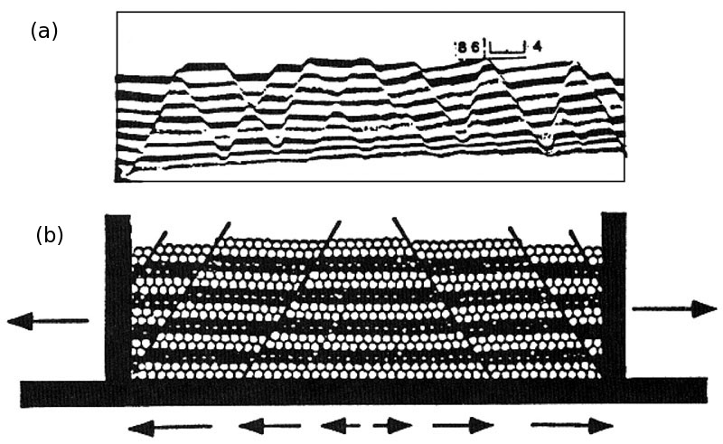
Many of the laboratory and numerical experiments under the plane strain condition, in fact, produce well-defined conjugate fault sets (Figure 2). These are documented under the headings just mentioned. However, deviations from the conjugate pattern containing two sets of faults occur quite frequently. These cases may be due to the switch of the relative magnitudes of the horizontal principal stresses. However, one of the most important reasons for the deviation from the classical conjugation pattern is that strain in nature may occur in 3D requiring more than two fault sets to accommodate it (Figure 1b).

Normal fault patterns produced (a) in a sandbox experiment (McClay and Ellis, 1987) and (b) a numerical experiment using Distinct Element Model (Saltzer and Pollard, 1992).Figure 2. Normal fault patterns produced (a) in a sandbox experiment (McClay and Ellis, 1987) and (b) a numerical experiment using Distinct Element Model (Saltzer and Pollard, 1992).

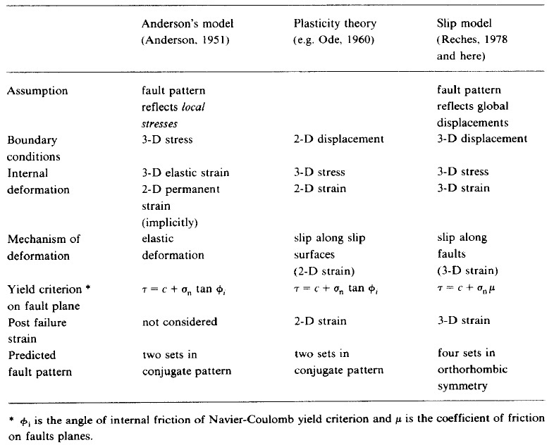
The table in Figure 3 includes a comparison between models of two conjugate sets of normal faults and four sets of normal faults with orthorhombic symmetry (Aydin and Reches, 1982; Reches, 1983). The specific orientations of the fault sets depend on the angle of internal friction, the friction coefficient, and the principal stress ratios.

Table summarizing various models of faulting and their predicted multiple fault sets. From Reches (1983). For Anderson model, see the details under 'Andersonian and Mohr-Coulomb Theory of Faulting.' For faulting of plastic rocks, see 'Slip Line Theory.'Figure 3. Table summarizing various models of faulting and their predicted multiple fault sets. From Reches (1983). For Anderson model, see the details under 'Andersonian and Mohr-Coulomb Theory of Faulting.' For faulting of plastic rocks, see 'Slip Line Theory.'

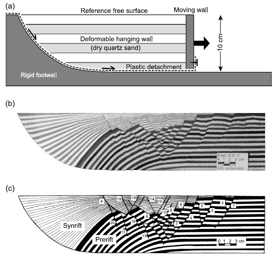
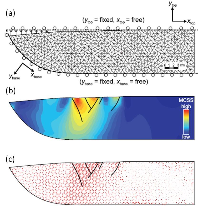
Another reason for the diversity of the normal fault patterns that should be mentioned here is that normal faults sometimes have listric geometry (Figures 4(a) and (b)) causing tilting, rotation, and the related heterogeneous stress and strain distribution. This would produce fault patterns different than those formed in homogeneous stress and strain fields. Figure 5(a) shows FEM mesh and boundary conditions used by Maerten and Maerten (2006) to calculate the distribution and orientation of the maximum Coulomb shear stresses shown in Figures 5(b) and (c), respectively, to justify the location and orientation of the faults in the laboratory experiments (Figure 4) by McClay (1983).

Experimental and numerical models of faults in sand layers above a listric normal fault at the interface of a rigid substrate and the deformable sediment cover. From Maerten and Maerten (2006) with reference to McClay, K.R. (1990).Figure 4. Experimental and numerical models of faults in sand layers above a listric normal fault at the interface of a rigid substrate and the deformable sediment cover. From Maerten and Maerten (2006) with reference to McClay, K.R. (1990).
Geomechanical model configuration to simulate the physical experiments in Figure 3 from McClay (1990). (a) FEM mesh and the boundary conditions of the numerical experiment. The calculated maximum Coulumb shear stress (MCSS) distribution (b) and orientations (c). From Maerten and Maerten (2006).Figure 5. Geomechanical model configuration to simulate the physical experiments in Figure 3 from McClay (1990). (a) FEM mesh and the boundary conditions of the numerical experiment. The calculated maximum Coulumb shear stress (MCSS) distribution (b) and orientations (c). From Maerten and Maerten (2006).
Types of Mechanisms and Mechanics of Multiple Normal Fault Sets:
North Sea Fault In-fill Modeling
Reference:

Anderson, E.M., 1951. Dynamics of faulting and dyke formation with application to Britain. Hafner Publishing Company, 206p.

Aydin, A., Reches, Z., 1982. The number and orientation of fault sets in the field and in laboratory. Geology 10: 107-112.

Maerten, L., Maerten, F., 2006. Chronologic modeling of faulted and fractured reservoirs using geomechanically-based restoration: Technique and industry applications. AAPG Bulletin 90: 1201-1226.

McClay, K.R., 1990. Deformation mechanics in analogue models of extensional fault systems, in E.H. Rutter and R. J. Knipe, eds., Deformation mechanisms, rheology and tectonics. Geological Society Special Publication 54: 445-454.

Ode, M., 1960. Faulting as a velocity discontinuity in plastic deformation. In: D. Griggs and J. Handin (Eds.), Rock Deformation. Geological Society of America, Memoirs 79: 343-393.

Reches, Z., 1983. Faulting of rocks in three-dimensional strain fields-II. Theoretical analysis. Tectonophysics 95: 133-156.

Younes, A.I., Aydin, A., 1998. Gulf of Suez Field Trip Guidebook. The Stanford Shale Smear Project 1998 Field Trip Guide. Stanford Digital Repository. Available at: http://purl.stanford.edu/jp025yc8745.


Readme    |    About Us    |    Acknowledgement    |    How to Cite    |    Terms of Use    |    Ⓒ Rock Fracture Knowledgebase