| |||||||
|
|
|||||||
|
|
|||||||
| Growth of Orthogonal Joint Sets | |||||||
|
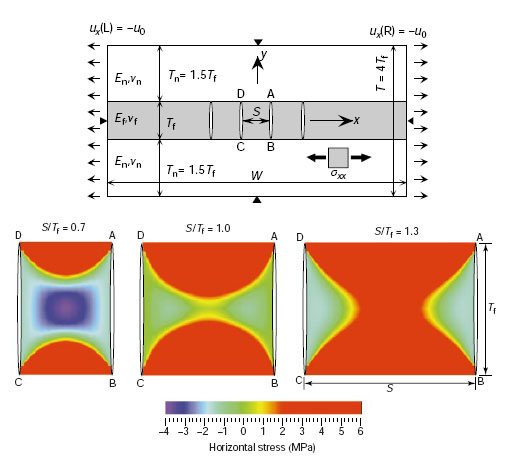
Local stress switch refers to the switch between the orientation of the maximum and minimum principal stresses in layered rocks. It helps to explain the formation of orthogonal joint sets. In layered rocks, especially thinly bedded ones, the spacing of joint set is mechanically related to the layer thickness or the height of the joints. After a single fracture forms, the strain accommodated by the fracture locally releases the stress forming the fracture in a region whose horizontal dimension scales with joint depth. In layered rock, since fractures may terminate at the layer boundary, its height is limited by the bed-thickness of the deformed layer, thus the horizontal dimension of the stress-released region is also limited. As the fracture set develops by infilling, the stress-released region may eventually overlap, after which no new parallel fracture can form, but perpendicular ones can. Under regional extensional environment, Bai et al. (2000) used numerical simulation (Figure 1) to show that when the joint spacing to layer thickness ratio changes from less than to greater than a value of about 1.0, the joint-perpendicular stress between adjacent joints changes from extensional (red) to compressive (blue). This stress switch prohibits the formation of infilling joints that parallel the original joints, and instead may cause the formation of the cross joint set. Orthogonal joint sets may thus form. Bai et al. (2002) further show that this switch occurs only when the Horizontal Remote Principal Stress Ratio is greater than a threshold value (~0.2).
Under regional compression environment, on the other hand, orthogonal pressure solution seam sets may form. During the formation of the systemic pressure solution seam set, the maximum compressive stress gradually decreases. At some stage, the maximum and the minimum compressive stress direction may switch and the orthogonal cross pressure solution seam sets may form. | |||||||
| Reference: |
|||||||
| Bai, T., 1998 Bai, T., Pollard, D.D., Gao, H., 2000 Bai, T., Maerten, L., Gross, M.R., Aydin, A., 2002 |
|||||||
|
Readme | About Us | Acknowledgement | How to Cite | Terms of Use | Ⓒ Rock Fracture Knowledgebase |
|||||||