Rock Fracture
KNOWLEDGEBASE
  

Initiation of Joints

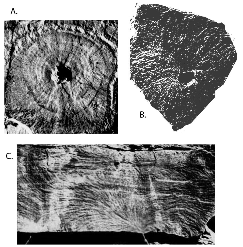
Joints, similar to other discontinuities such as faults and pressure solution seams, initiate at flaws including inclusions, crystal defects, grain contacts, cavity and pores, fossils, sole marks, and cusps (Figure 1). Joints initiate at flaws because flaws with different elastic properties than the surrounding rock perturb the stress field. There are two circumstances that are important and we discuss these in the next two paragraphs.

Photos showing joint initiation at various flaws. A. Joint initiation from a dissolution-related cavity in limestone. Courtesy of R. Weinberger. B. Thermal fracture initiation from air bubbles in volcanic rock. C. From irregular bedding in layered sedimentary rock. B and C from Pollard and Aydin (1988).Figure 1. Photos showing joint initiation at various flaws. A. Joint initiation from a dissolution-related cavity in limestone. Courtesy of R. Weinberger. B. Thermal fracture initiation from air bubbles in volcanic rock. C. From irregular bedding in layered sedimentary rock. B and C from Pollard and Aydin (1988).

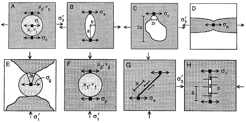
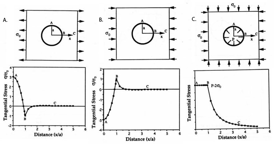
Flaws can amplify tensile stress. The concentration of local stress at flaws may drive the initiation and propagation of a joint under a remote stress insufficient by itself to cause jointing. For stiff inclusions, a remote tensile stress can be amplified by a factor up to 1.5 inside the inclusion. For soft circular inclusions or cavities, stress at the surrounding rock around the inclusion is amplified. For example, for a spherical cavity with a circular section, this amplification is equal to a factor of 3 (Figure 2A; Figure 3A, point A). For an elliptical cavity, the amplification factor depends on the shape or sharpness of the inclusion or cavity instead of its size; the larger the axial ratio, a over b in Figure 2B and r over a in 2C, the larger the maximum amplification factor. The local maximum tensile stress occurs where the radius of curvature is the smallest. For a long and thin cavity, the magnitude of the stress at the tip can be many times that of the applied remote stress. Stress concentration allows us to make important inferences. For two flaws with unequal lengths subjected to the same increasing driving stress, the longer or slimmer one will meet the propagation criterion first.

Idealizations of joint-initiation mechanisms based on stress concentration as well as changing background compressive stresses into local tensile stresses. A. Circular inclusion under uniaxial tension. B. Elliptical hole under uniaxial tension. C. Irregular cavity under uniaxial tension. D. Cusp in a stretched layer. E. Circular grain compressed between two grains. F. Circular inclusion under uniaxial compression. G. Inclined elliptical hole under uniaxial compression. H. An elliptical hole perpendicular to a remote uniaxial compression and internal pressure. In All cases, a is a length, u is the elastic shear modulus, v is Poisson's ratio, p is internal fluid pressure. From Pollard and Aydin (1988).Figure 2. Idealizations of joint-initiation mechanisms based on stress concentration as well as changing background compressive stresses into local tensile stresses. A. Circular inclusion under uniaxial tension. B. Elliptical hole under uniaxial tension. C. Irregular cavity under uniaxial tension. D. Cusp in a stretched layer. E. Circular grain compressed between two grains. F. Circular inclusion under uniaxial compression. G. Inclined elliptical hole under uniaxial compression. H. An elliptical hole perpendicular to a remote uniaxial compression and internal pressure. In All cases, a is a length, u is the elastic shear modulus, v is Poisson's ratio, p is internal fluid pressure. From Pollard and Aydin (1988).
Numerical models showing tangential stress distribution around circular flaws under uniaxial tension, compression, as well as biaxial hydrostatic stress and internal pore pressure. Stresses are normalized by the remote stresses. In C, the stress at points A and B are equal, they will be negative if p is greater than twice the hydrostatic stress. From Aydin (1996).Figure 3. Numerical models showing tangential stress distribution around circular flaws under uniaxial tension, compression, as well as biaxial hydrostatic stress and internal pore pressure. Stresses are normalized by the remote stresses. In C, the stress at points A and B are equal, they will be negative if p is greater than twice the hydrostatic stress. From Aydin (1996).

Flaws can also induce local tensile stresses in an overall compressive environment. Figure 2E shows a grain at diametrical contact with two other grains, which results in tensile stress under an applied compressive stress. Figure 2F and Figure 3B (point B) show a cavity inducing tension of the same magnitude at two points at the cavity border. Figure 2G shows shearing induced tensile stress at the tip region of the sliding plane under compressive stress.

Figure 2H and Figure 3C show a common mechanism of joint initiation based on cavities or micro-cracks subjected to internal fluid pressure. Pore fluid pressure amplifies the stresses at the flaw tip in Figure 2H and neutralizes the hydrostatic pressure in Figure 3C.

Reference:

Aydin, A., 1996. Physical characteristics of fractures and fracture patterns. In: Rock Fractures and Fluid Flow (Chapter 2). National Academic Press, Washington, D.C., p. 29-101.

Pollard, D.D., Aydin, A., 1988. Progress in understanding jointing over the past century. Geological Society of America Bulletin 100 (8): 1181-1204.

Pollard, D.D., Fletcher, R.C., 2005. Fundamentals of Structural Geology. Cambridge University Press.


Readme    |    About Us    |    Acknowledgement    |    How to Cite    |    Terms of Use    |    Ⓒ Rock Fracture Knowledgebase