Rock Fracture
KNOWLEDGEBASE
  

Mechanisms and Mechanics of Joint Zones

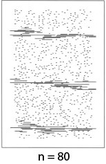
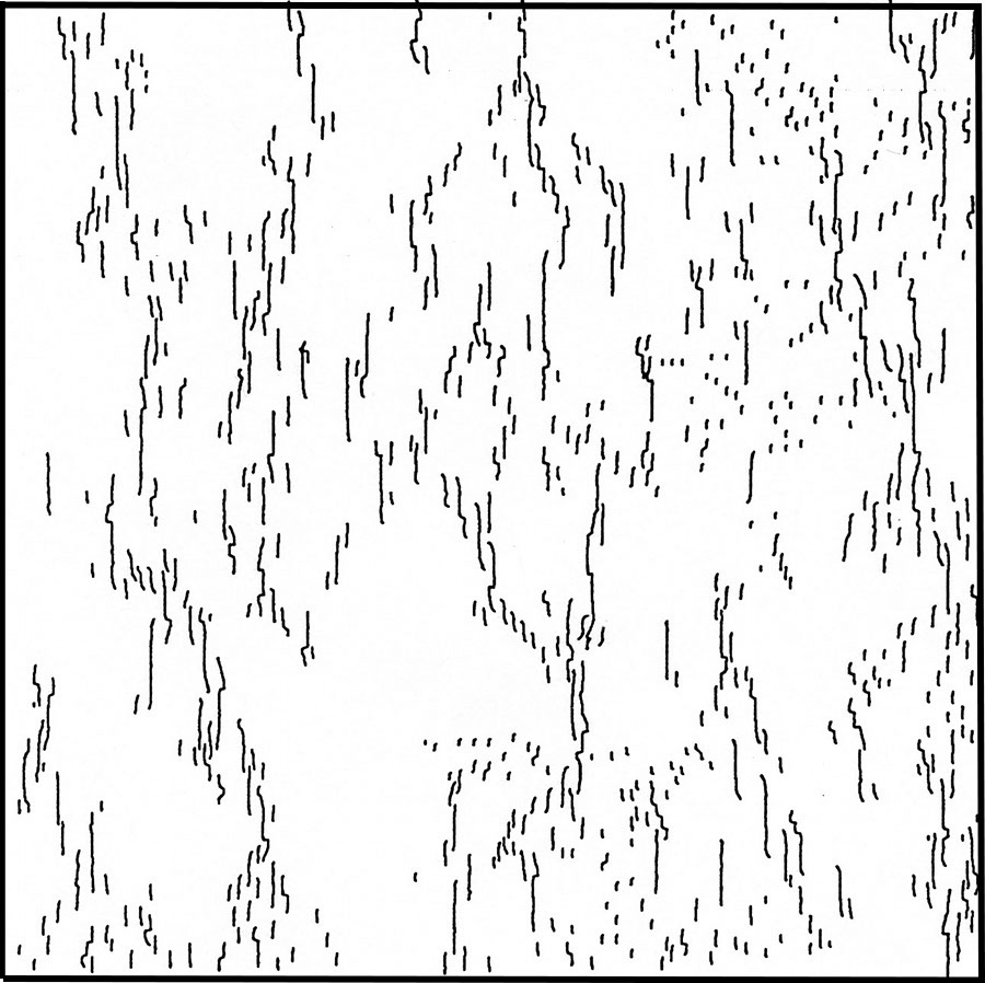
Two important factors which play an important role in joint zone formation are joint propagation velocity and joint interaction. Joint propagation velocity has been considered earlier and has been linked to subcritical index, the higher values of which result in localization of joints into distinct zones. For example, Figure 1 is a pattern produced by a numerical fracture mechanics model with a subcritical index value of 80 (Olson, 2004). Figure 2 illustrates a somewhat different joint pattern with joint zones with echelon joint architecture (Renshaw and Pollard, 1995) reflecting the influence of joint interaction on the joint alignment to form a zone (Du and Aydin, 1991).

Joint zones produced by a numerical fracture mechanics model with a subcritical index of 80. Points or short lines are the locations of initial flaws. Olson (2004).Figure 1. Joint zones produced by a numerical fracture mechanics model with a subcritical index of 80. Points or short lines are the locations of initial flaws. Olson (2004).
Development of joint zones with echelon patterns in numerical experiments. Courtesy of Carl Renshaw.Figure 2. Development of joint zones with echelon patterns in numerical experiments. Courtesy of Carl Renshaw.

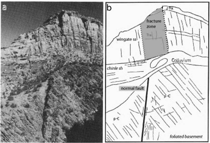
There are, of course, other means of producing joint localization. Strain localization around the tip areas of large scale structures (process zones and damage zones) and above buried faults may be considered in this category. Figure 3 shows joint and sheared joint localization into a well-defined zone in the Mesozoic Wingate Sandstone and Kayenta Formation above a basement normal fault in the Colorado Plateau. In the figure, the fracture zone in the cover above the basement fault has been highlighted for emphasis. From a similar perspective, a layer or formation or region with a significantly higher joint density than its surroundings may be referred to as a joint zone.

A fracture zone in the Wingate sandstone above a normal fault in crystalline basement rock. The Rattle Snake Canyon, Unprahgne uplift, UT. Slightly modified from Heyman (1983). The fracture zone visible in the photo (a) has been highlighted in the map (b), which was not shown by the original author.Figure 3. A fracture zone in the Wingate sandstone above a normal fault in crystalline basement rock. The Rattle Snake Canyon, Unprahgne uplift, UT. Slightly modified from Heyman (1983). The fracture zone visible in the photo (a) has been highlighted in the map (b), which was not shown by the original author.
Reference:

Du, Y., Aydin, A., 1991. Interaction of multiple cracks and formation of echelon crack arrays. International Journal of Analytical and Numerical Methods in Geomechanics 15: 205-218.

Heyman, O.G., 1983. Distribution and structural geometry of faults and folds along the northwestern uncompahgre uplift, western Colorado and eastern Utah. In: Averett, W. R. (ed.), Norhern Paradox Basin-Uncompahgre uplift, Field trip guide, Grand Junction Geological Society: 53-57.

Kelly, P.G., Sanderson, D.J., Peacock, D.C.P., 1998. Linkage and evolution of conjugate strike-slip fault zones in limestones of Somerset and Northumbria. Journal of Structural Geology 20: 1477-1493.

Olson, J., 2004. Predicting fracture swarms - the influence of subcritical crack growth and the crack-tip process zone on joint spacing in rock. The Initiation, Propagation, and Arrest of Joints and Other Fractures. Geological Society, London, Special Publications 231: 73-87.


Readme    |    About Us    |    Acknowledgement    |    How to Cite    |    Terms of Use    |    Ⓒ Rock Fracture Knowledgebase