Rock Fracture
KNOWLEDGEBASE
  

Mechanisms and Mechanics of Joint Domains

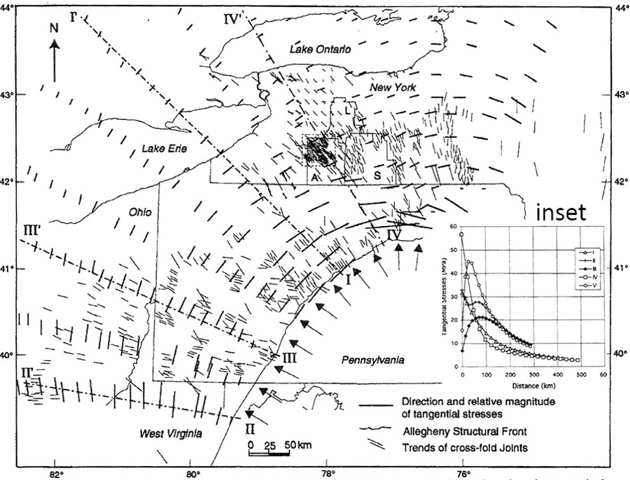
One of the simplest mechanisms that may result in the formation of different joint domains is the temporal and spatial variation of the stresses in response to a certain loading system or systems. This mechanism has been proposed for the variation of joint orientation along the Appalachian Mountain belt as seen in Figure 1 (Zhao and Jacobi, 1997). The authors used a Displacement Discontinuity Boundary Element Model to investigate a possible mechanism for the formation of the cross-joint system along the northern Appalachian Mountain Belt described in the 'Joint Domains' section. The driving stress of 50 MPA in the horizontal direction was assumed to be applied on the eastern Allegheny boundary. Then, the direction and relative magnitude of the tangential stresses (thick marks and inset) were calculated. The authors proposed that the model results in terms of strains are consistent with the observed and calculated data.

Displacement Discontinuity Boundary Element Model results to investigate a possible mechanism for the formation of the cross-joint pattern along the northern Appalachian Mountain Belt described in Joint Domains section. The driving stress of as much as 50 MPA in horizontal direction was assumed to be applied on the eastern Allegheny boundary. Then, the direction and relative magnitude of the tangential stresses (thick marks and inset) were calculated. From Zhao and Jacobi (1997).Figure 1. Displacement Discontinuity Boundary Element Model results to investigate a possible mechanism for the formation of the cross-joint pattern along the northern Appalachian Mountain Belt described in Joint Domains section. The driving stress of as much as 50 MPA in horizontal direction was assumed to be applied on the eastern Allegheny boundary. Then, the direction and relative magnitude of the tangential stresses (thick marks and inset) were calculated. From Zhao and Jacobi (1997).

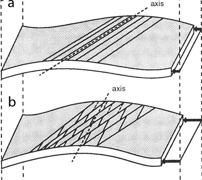
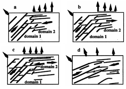
A mechanism similar to the one above has also been tested in the laboratory using brittle coating techniques and sequential bending of a plate about different axes (Figure 2) as described under 'Mechanisms and Mechanics of Multiple Joint Sets' (Rives and Petit, 1990). All four diagrams in Figure 3 from Wu (1992) illustrate two joint domains and the details of their conjoining areas in response to four different loading configurations as shown by the direction and relative lengths of the arrows at the boundaries of the plates with brittle coating. The first two diagrams show non-uniform distribution of boundary stresses. In Figure 3a, the prominent joints in domain 1 propagated from right to left while the prominent joints in domain 2 propagated from left to right and intersected the major set of domain 1. Note that the growth directions of the sets are marked by arrows within the frames. Figure 3b represents a case in which the transition from the major set in domain 1 to domain 2 is continuous perhaps due to the decreasing boundary stresses from right to left. The growth direction of the major joint set of domain 2 in Figure 3c is bimodal but the overall pattern is similar to those in (a) and (b). In all three loading configurations, the transitions from one domain to the other are sharp and some short joints appear between the systematic joints. If the boundary stresses have the same magnitude but change orientation gradually from one side to the other (Figure 3d), there is a noticeable smooth transition from one systematic set to the other. Furthermore, some joints in the intersection region have orientations between the two systematic sets.

A PVC plate with a brittle varnish coating was subjected to first torsion or non-cylindrical bending (a) and then bending about a cylindrical axis (b) to produce two sets of joints. From Rives and Petit (1990).Figure 2. A PVC plate with a brittle varnish coating was subjected to first torsion or non-cylindrical bending (a) and then bending about a cylindrical axis (b) to produce two sets of joints. From Rives and Petit (1990).
The effect of local stress distribution on the joint patterns in the intersection region between two domains. In All four cases, bending was applied first to the lower left part, then a different distribution of stress was applied to the top boundary. In (a) boundary stress decreases from right to left in domain 2. (b) Boundary stress increases from right to left in domain 2. (c) Boundary stress is uniformly distributed. (d) The maximum stress orientation changes continuously from domain 1 to domain 2. From Wu (1992). See also Cruikshank and Aydin (1995).Figure 3. The effect of local stress distribution on the joint patterns in the intersection region between two domains. In All four cases, bending was applied first to the lower left part, then a different distribution of stress was applied to the top boundary. In (a) boundary stress decreases from right to left in domain 2. (b) Boundary stress increases from right to left in domain 2. (c) Boundary stress is uniformly distributed. (d) The maximum stress orientation changes continuously from domain 1 to domain 2. From Wu (1992). See also Cruikshank and Aydin (1995).

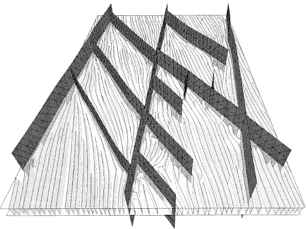
One of the most common mechanisms for creating spatially varying joint patterns is fault interaction and the associated stress perturbation around the interacting faults. Joints and veins associated with interacting echelon strike slip faults (Segall and Pollard, 1980) and/or sub-parallel thrust faults (Ohlmacher and Aydin, 1997) were modeled. An example of this mechanism from Bourne and Willemse (2001) who used a similar approach to investigate the orientation and distribution of joints between two intersecting sets of shear fractures is given here (Figure 4). Analysis similar to these cases were also presented by Rawnsley et al. (1992) and Kattenhorn et al. (2000) in this Knowledgebase.

Joint patterns around a network of strike-slip faults based on 3D elastic modeling. Notice the pattern variation near fault intersections. From Bourne and Willemse (2001).Figure 4. Joint patterns around a network of strike-slip faults based on 3D elastic modeling. Notice the pattern variation near fault intersections. From Bourne and Willemse (2001).

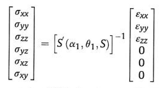
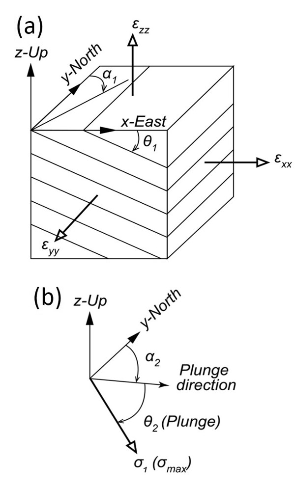
A somewhat different mechanism producing joint networks with various domains occurs in eolian sandstone as shown in the map given in 'Joint Domains' (Deng et al., 2015). This mechanism is based on stress perturbation associated with cross-bedding related anisotropy. Figures 5a and 5b show the model configuration. Equation 1 is Hooke's Law written in terms of the angular parameters illustrated in the configuration in Figure 5.

The Hooke's Law in terms of the angular parameters defined in 5a. From Deng et al. (2015).Equation 1. The Hooke's Law in terms of the angular parameters defined in 5a. From Deng et al. (2015).
Model configuration showing (a) strike of cross-bedding (α1), dip-angle (θ1), and the three principal strain components applied in the Cartesian coordinate system (x, y, z). (b) Diagram showing plunge direction (α2) and plunge (θ2) of the maximum tensile stress component (σ1). From Deng et al. (2015).Figure 5. Model configuration showing (a) strike of cross-bedding (α1), dip-angle (θ1), and the three principal strain components applied in the Cartesian coordinate system (x, y, z). (b) Diagram showing plunge direction (α2) and plunge (θ2) of the maximum tensile stress component (σ1). From Deng et al. (2015).

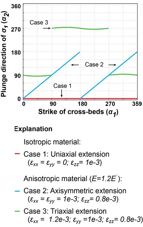
Figure 6 shows the orientation of the largest tensile principal stress as a function of a range of strike values of cross-bedding with an average dip angle of 21 degrees under three loading systems: uniaxial tension, axisymmetric, and three-dimensional extension. We refer to the original publication for details, but here it suffices to say that a combination of depositional cross-bedding in various orientation and basic loading configurations may produce a wide variety of joint domains assuming that the orientation of joints will depend on the orientation of the local greatest tensile stress.

Model results showing the plunge direction of the greatest tensile stress as a function of a range of strike of cross-bedding and three cases (1 to 3) defined in the explanation under the diagram in terms of the applied boundary strains. Notice that Case 1 is for uniaxial extension and has the same plunge direction for only cross-bed strikes. From Deng et al. (2015).Figure 6. Model results showing the plunge direction of the greatest tensile stress as a function of a range of strike of cross-bedding and three cases (1 to 3) defined in the explanation under the diagram in terms of the applied boundary strains. Notice that Case 1 is for uniaxial extension and has the same plunge direction for only cross-bed strikes. From Deng et al. (2015).
Reference:

Bourne, S.J., Willemse, E.J.M, 2001. Elastic stress control on the pattern of tensile fracturing around a small fault network at Nash Point, UK. Journal of Structural Geology 23: 1753-1770.

Cruikshank, K.M., Aydin, A., 1995. Unweaving the joints in Entrada Sandstone, Arches National Park, Utah, U.S.A.. Journal of Structural Geology 17: 409-421.

Deng, S., Cilona, A., Morrow, C., Mapeli, C., Liu, C., Lockner, D., Prasad, M., Aydin, A., 2015. Cross-bedding related anisotropy and its interplay with various boundary conditions in the formation and orientation of joints in an Aeolian sandstone. Journal of Structural Geology 77: 175-190.

Kattenhorn, S., Aydin, A., Pollard, D.D., 2000. Joints at high angles to normal fault strike: An explanation using 3-D numerical models of fault-perturbed stress field. Journal of Structural Geology 22: 1-23.

Ohlmacher, G., Aydin, A., 1997. Mechanics of vein, fault and solution surface formation in the Appalachian Valley and Ridge, northeastern Tennesssee, U.S.A: implications for fault friction state of stress and fluid pressure. Journal of Structural Geology 19: 927-944.

Rawnsley, K.D., Rives, T., Hencher, S.R., Lumsden, A.C., 1992. Joint development in perturbed stress fields near faults. Journal of Structural Geology 14: 939-951.

Rives, T., Petit, J.P., 1990. Experimental study of jointing during cylindrical and non-cylindrical folding. In Rossmanith, H. P. (ed.), Mechanics of jointed and faulted rock, 205-211, A. A. Balkema, Rotterdam.

Segall, P., Pollard, D.D., 1980. Mechanics of discontinuous faults. Journal of Geophysical Research 85: 4337-4350.

Wu, H., 1992. Experimental simulation of the formation of multiple joint domains. Stanford Digital Repository. Available at: http://purl.stanford.edu/tb279bf0367.

Zhao, G., Jacobi, R.D., 1997. Formation of regional cross-fold joints in the northern Appalachian plateau. Journal of Structural Geology 19: 817–834.


Readme    |    About Us    |    Acknowledgement    |    How to Cite    |    Terms of Use    |    Ⓒ Rock Fracture Knowledgebase